
Homework Answers
Add Answer to:
Three resistors with their respective values are shown in the circuit diagram below. The voltage between...
6 & 7 Three resistors with their respective values are shown in the circuit diagram below....
 6 & 7
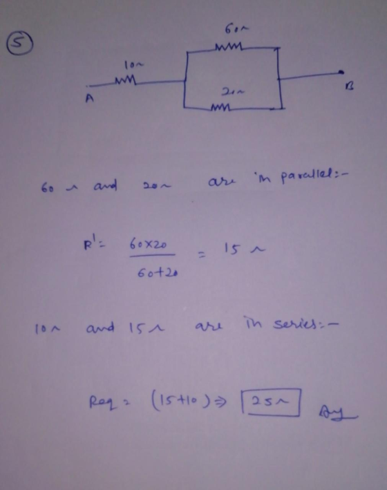
Three resistors with their respective values are shown in the circuit diagram below. The voltage between terminals A and B is 30 V. 5. What is the equivalent resistor between terminal A and B? (Show your work) 60 g 20 | F.g.1 6. Using the data circuit above to Complete the table below (Show your work). R (12) AV() 1(A) 20 7. In Fig. 1, if the 10- resistor is replaced by a 100-F capacitor, the circuit...
6 & 7
Three resistors with their respective values are shown in the circuit diagram below. The voltage between terminals A and B is 30 V. 5. What is the equivalent resistor between terminal A and B? (Show your work) 60 g 20 | F.g.1 6. Using the data circuit above to Complete the table below (Show your work). R (12) AV() 1(A) 20 7. In Fig. 1, if the 10- resistor is replaced by a 100-F capacitor, the circuit...
Three resistors with their respective values are shown in the circuit diagram below. The voltage between...
 Three resistors with their respective values are shown in the circuit diagram below. The voltage between terminals A and B is 30 V. 5. What is the equivalent resistor between terminal A and B? (Show your work) 60 man 20 F.g.1
Three Resistors in Parallel Three resistors are connected in parallel as shown in figure (a). A...
 Three Resistors in Parallel Three resistors are connected in parallel as shown in figure (a). A potential difference of 12.0V is maintained between points a and b. Three resistors connected in parallel. The Another circuit with three resistors and a voltage across each resistor is 12.0 V. battery. Is it equivalent to the circuit in (a)? a Ž 3.00 6.00 9.00 3.00 6.00 09.00 (a) Calculate the equivalent resistance of the circuit. SOLUTION Conceptualize Figure (a) shows that we are...
Four resistors are connected to a battery with a terminal voltage of 12 v, as shown...
 Four resistors are connected to a battery with a terminal voltage of 12 v, as shown in the figure below. Use the following variables as neoessaryn Ru 40.0 n and Ra *70.0 in. (a) How would you reduce the circuit to an equivalent single resistor connected to the battery? Uee this to find the equvalent resatance ofthe ercuz. procedure (b) Find the current delivered by the battery to this equivalent resistance. (c) Determine the power delivered by the battery. (d)...
A circuit is constructed with five resistors and a battery as shown. The values for the...
 A circuit is constructed with five resistors and a battery as shown. The values for the resistors are: R1 = R5 = 43 A, R2 = 121 , R3 = 64, and R4 = 1300. The battery voltage is V = 12 V. R1 b 4 Ra R5 1) What is Rab, the equivalent resistance between points a and b? 76.92 Submit 2) What is Rac, the equivalent resistance between points a and c? 119.9 Submit 3) What is 15,...
I need help trying to design this RC-circuit. PHYS 2120 LAB 6 - RC Circuit Capstone...
 I need help trying to design this RC-circuit.
PHYS 2120 LAB 6 - RC Circuit Capstone For example, if we wait long enough, eventually what do you expect the voltage over the capacitor to become? Part 1: Design an RC-circuit to charge a capacitor as quickly as possible. Your circuit must include the following elements (and only these elements): A Switch, a 10V Battery, a 0.1 F Capacitor, a 250 resistor, a 500 resistor, two 7512 resistors, a 1000 resistor,...
I need help trying to design this RC-circuit.
PHYS 2120 LAB 6 - RC Circuit Capstone For example, if we wait long enough, eventually what do you expect the voltage over the capacitor to become? Part 1: Design an RC-circuit to charge a capacitor as quickly as possible. Your circuit must include the following elements (and only these elements): A Switch, a 10V Battery, a 0.1 F Capacitor, a 250 resistor, a 500 resistor, two 7512 resistors, a 1000 resistor,...
the equivalent resistance between points A and B in the circuit shown below is 26 ohm,...
 the equivalent resistance between points A and B in the
circuit shown below is 26 ohm, a) find value of resistance R. b) a
12 v battery is connected to terminals A and B. find the current in
each resistors and power dissipated by each resistors
University Physics I (PHYS 23261 University Physics II (PHYS 2326) Houston Community College 7/26/2018 Quiz: Chap. 27 & 28 Show your solution to get full credit. 1· The equivalent resistance between points A and...
the equivalent resistance between points A and B in the
circuit shown below is 26 ohm, a) find value of resistance R. b) a
12 v battery is connected to terminals A and B. find the current in
each resistors and power dissipated by each resistors
University Physics I (PHYS 23261 University Physics II (PHYS 2326) Houston Community College 7/26/2018 Quiz: Chap. 27 & 28 Show your solution to get full credit. 1· The equivalent resistance between points A and...
Four resistors are connected to a battery with a terminal voltage of 12 V, as shown...
 Four resistors are connected to a battery with a terminal
voltage of 12 V, as shown in the figure below. (Assume
R1 = 31.0 Ω and R2 = 70.0
Ω.)
(a) How would you reduce the circuit to an equivalent single
resistor connected to the battery? Use this procedure to find the
equivalent resistance of the circuit.
Ω
(b) Find the current delivered by the battery to this equivalent
resistance.
A
(c) Determine the power delivered by the battery.
W...
Four resistors are connected to a battery with a terminal
voltage of 12 V, as shown in the figure below. (Assume
R1 = 31.0 Ω and R2 = 70.0
Ω.)
(a) How would you reduce the circuit to an equivalent single
resistor connected to the battery? Use this procedure to find the
equivalent resistance of the circuit.
Ω
(b) Find the current delivered by the battery to this equivalent
resistance.
A
(c) Determine the power delivered by the battery.
W...
Draw a circuit diagram that has two resistors in parallel with a DC voltage source. If...
Draw a circuit diagram that has two resistors in parallel with a DC voltage source. If resistor one (R1) is 252 kohms and resistor two (R2) is 176 kohms, then what is the current flowing through the circuit if the voltage is 3.16 V? What is the power flowing through the circuit?
For the circuit of Figure 1, choose values for resistors R1, R2, and R3
 C.la For the circuit of Figure 1, choose values for resistors R1, R2, and R3(all resistances must be greater than one Kilo ohm). Given that the voltage source Vs1 = 8V and Vs2 = 10V determine the output voltage Vout. C.1b For the same resistor values Ri, R2, and Rs you chose in part C.la Given that the voltage source Vsi = 8V and Vs2 = 10V, use Figure 2(a) to determine the output voltage Vout/ and Figure 2(b) to determine the output voltage Vout2. Discussion:...
 6 & 7
Three resistors with their respective values are shown in the circuit diagram below. The voltage between terminals A and B is 30 V. 5. What is the equivalent resistor between terminal A and B? (Show your work) 60 g 20 | F.g.1 6. Using the data circuit above to Complete the table below (Show your work). R (12) AV() 1(A) 20 7. In Fig. 1, if the 10- resistor is replaced by a 100-F capacitor, the circuit...
6 & 7
Three resistors with their respective values are shown in the circuit diagram below. The voltage between terminals A and B is 30 V. 5. What is the equivalent resistor between terminal A and B? (Show your work) 60 g 20 | F.g.1 6. Using the data circuit above to Complete the table below (Show your work). R (12) AV() 1(A) 20 7. In Fig. 1, if the 10- resistor is replaced by a 100-F capacitor, the circuit...
 Three resistors with their respective values are shown in the circuit diagram below. The voltage between terminals A and B is 30 V. 5. What is the equivalent resistor between terminal A and B? (Show your work) 60 man 20 F.g.1
 Three Resistors in Parallel Three resistors are connected in parallel as shown in figure (a). A potential difference of 12.0V is maintained between points a and b. Three resistors connected in parallel. The Another circuit with three resistors and a voltage across each resistor is 12.0 V. battery. Is it equivalent to the circuit in (a)? a Ž 3.00 6.00 9.00 3.00 6.00 09.00 (a) Calculate the equivalent resistance of the circuit. SOLUTION Conceptualize Figure (a) shows that we are...
 Four resistors are connected to a battery with a terminal voltage of 12 v, as shown in the figure below. Use the following variables as neoessaryn Ru 40.0 n and Ra *70.0 in. (a) How would you reduce the circuit to an equivalent single resistor connected to the battery? Uee this to find the equvalent resatance ofthe ercuz. procedure (b) Find the current delivered by the battery to this equivalent resistance. (c) Determine the power delivered by the battery. (d)...
 A circuit is constructed with five resistors and a battery as shown. The values for the resistors are: R1 = R5 = 43 A, R2 = 121 , R3 = 64, and R4 = 1300. The battery voltage is V = 12 V. R1 b 4 Ra R5 1) What is Rab, the equivalent resistance between points a and b? 76.92 Submit 2) What is Rac, the equivalent resistance between points a and c? 119.9 Submit 3) What is 15,...
 I need help trying to design this RC-circuit.
PHYS 2120 LAB 6 - RC Circuit Capstone For example, if we wait long enough, eventually what do you expect the voltage over the capacitor to become? Part 1: Design an RC-circuit to charge a capacitor as quickly as possible. Your circuit must include the following elements (and only these elements): A Switch, a 10V Battery, a 0.1 F Capacitor, a 250 resistor, a 500 resistor, two 7512 resistors, a 1000 resistor,...
I need help trying to design this RC-circuit.
PHYS 2120 LAB 6 - RC Circuit Capstone For example, if we wait long enough, eventually what do you expect the voltage over the capacitor to become? Part 1: Design an RC-circuit to charge a capacitor as quickly as possible. Your circuit must include the following elements (and only these elements): A Switch, a 10V Battery, a 0.1 F Capacitor, a 250 resistor, a 500 resistor, two 7512 resistors, a 1000 resistor,...
 the equivalent resistance between points A and B in the
circuit shown below is 26 ohm, a) find value of resistance R. b) a
12 v battery is connected to terminals A and B. find the current in
each resistors and power dissipated by each resistors
University Physics I (PHYS 23261 University Physics II (PHYS 2326) Houston Community College 7/26/2018 Quiz: Chap. 27 & 28 Show your solution to get full credit. 1· The equivalent resistance between points A and...
the equivalent resistance between points A and B in the
circuit shown below is 26 ohm, a) find value of resistance R. b) a
12 v battery is connected to terminals A and B. find the current in
each resistors and power dissipated by each resistors
University Physics I (PHYS 23261 University Physics II (PHYS 2326) Houston Community College 7/26/2018 Quiz: Chap. 27 & 28 Show your solution to get full credit. 1· The equivalent resistance between points A and...
 Four resistors are connected to a battery with a terminal
voltage of 12 V, as shown in the figure below. (Assume
R1 = 31.0 Ω and R2 = 70.0
Ω.)
(a) How would you reduce the circuit to an equivalent single
resistor connected to the battery? Use this procedure to find the
equivalent resistance of the circuit.
Ω
(b) Find the current delivered by the battery to this equivalent
resistance.
A
(c) Determine the power delivered by the battery.
W...
Four resistors are connected to a battery with a terminal
voltage of 12 V, as shown in the figure below. (Assume
R1 = 31.0 Ω and R2 = 70.0
Ω.)
(a) How would you reduce the circuit to an equivalent single
resistor connected to the battery? Use this procedure to find the
equivalent resistance of the circuit.
Ω
(b) Find the current delivered by the battery to this equivalent
resistance.
A
(c) Determine the power delivered by the battery.
W...
 C.la For the circuit of Figure 1, choose values for resistors R1, R2, and R3(all resistances must be greater than one Kilo ohm). Given that the voltage source Vs1 = 8V and Vs2 = 10V determine the output voltage Vout. C.1b For the same resistor values Ri, R2, and Rs you chose in part C.la Given that the voltage source Vsi = 8V and Vs2 = 10V, use Figure 2(a) to determine the output voltage Vout/ and Figure 2(b) to determine the output voltage Vout2. Discussion:...
Most questions answered within 3 hours.
-
Where is the error in this code sequence?
String s1 = "Hello";
String s2 = "ello";...
asked 10 months ago -
Financial data for Joel de Paris, Inc., for last year
follow:
Joel de Paris, Inc.
Balance...
asked 10 months ago -
Consider this reaction:
Al2(SO4)3 (aq)+ BaCl3
(aq) Al2Cl6 (aq)- +
3BaSO4(s) . What is the...
asked 10 months ago -
Suppose that Savneet is considering increasing her
recent random sample from 20 car rentals to 40...
asked 10 months ago -
Trucks arrive at an unloading terminal at an average rate of 120
per hour.
Trucks arrive...
asked 10 months ago -
Why are methanol and ethanol completely soluble in water while
octanol is not very little soluble....
asked 10 months ago -
A facilities manager at a university reads in a research report
that the mean amount of...
asked 10 months ago -
When the CuSO4 is rehydrated by adding water to the anhydrous
compound, is this an endothermic...
asked 10 months ago -
A ray of sunlight is passing from diamond into crown glass; the
angle of incidence is...
asked 10 months ago -
A block of mass 0.249 kg is placed on top of a light, vertical
spring of...
asked 10 months ago -
how do the kidneys compensate in the presences of acidosis
a) trigger hyperventilate
b) reserve acid...
asked 10 months ago -
Question 501 pts
The rental rate of capital to the firm increases. Which of the
following...
asked 10 months ago