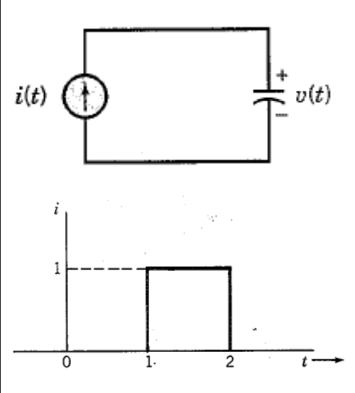
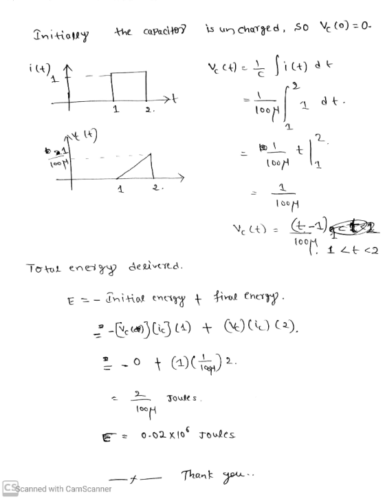
In the adjoining circuit schematic, the capacitor has a capacitance C = 100 uF, and is uncharged initially (at t = 0). The current source i(t) delivers a square pulse of current as shown in the figure, with its time dependence described algebraically as:

Homework Answers
Add Answer to:
In the adjoining circuit schematic, the capacitor has a
capacitance C = 100 uF, and is...
2502 In the adjoining circuit schematic, in steady-state, the current flowing through the loop causes a...
 2502 In the adjoining circuit schematic, in steady-state, the current flowing through the loop causes a voltage drop across the resistor, having the waveform vr(t) = 15 cos (75 t) and a voltage drop across the capacitor given by ve(t) = 20 cos (75 t +90°) (a) Express the above two voltages in phasor form. (b) Find the source voltage shown in the circuit schematic, expressed in phasor form. (c) Express the source voltage v(t) as a function of time....
In the adjoining circuit schematic, in steady-state, the current flowing through the loop causes a voltage...
 In the adjoining circuit schematic, in steady-state, the current
flowing through the loop causes a voltage drop across the resistor,
having the waveform
vR(t) = 15 cos (75 t) and a voltage drop across the capacitor
given by vC(t) = 20 cos (75 t + 90⁰)
(a) Express the above two voltages in phasor form. (b) Find the
source voltage shown in the circuit schematic, expressed in phasor
form. (c) Express the source voltage v(t) as a function of
time....
In the adjoining circuit schematic, in steady-state, the current
flowing through the loop causes a voltage drop across the resistor,
having the waveform
vR(t) = 15 cos (75 t) and a voltage drop across the capacitor
given by vC(t) = 20 cos (75 t + 90⁰)
(a) Express the above two voltages in phasor form. (b) Find the
source voltage shown in the circuit schematic, expressed in phasor
form. (c) Express the source voltage v(t) as a function of
time....
250 22 Problem 3. (9 Points) In the adjoining circuit schematic, in steady-state, the current flowing...
 250 22 Problem 3. (9 Points) In the adjoining circuit schematic, in steady-state, the current flowing through the loop causes a voltage drop across the resistor, having the waveform vr(t) = 15 cos (75 t) and a voltage drop across the capacitor given by ve(t) = 20 cos (75 t +90) (a) Express the above two voltages in phasor form. (b) Find the source voltage shown in the circuit schematic, expressed in phasor form. (c) Express the source voltage v(t)...
An AC power supply is connected to a capacitor of capacitance 7.5 uF
An AC power supply is connected to a capacitor of capacitance 7.5 uF. At time t=0 the power supply is switched on and starts providing a time-dependent voltage v(t)=V0cos(ωt) across the capacitor, where V0=5.3 V and ω=374 rad/s. The capacitor is initially uncharged. Part ( a) Find the current, in milliamperes with its sign, through the capacitor at time t=1.5 s.
Problem 1: Draw the waveform for the current in 12 - uF when the capacitor voltage...
 Problem 1: Draw the waveform for the current in 12 - uF when the capacitor voltage is as described in the following schematic. The current plot has to be labeled with units and numbers. v(t) (V) 12 10 16 0 6 1 (us) -8
01 The capacitor in the circuit to the left below is initially uncharged. It is connected...
 01 The capacitor in the circuit to the left below is initially uncharged. It is connected to a voltage source that produces a voltage given to the right in the figure below. Plot the current through the capacitor as a function of time. Label your plot, write values and units it v(V) 10 HF 02 The switch in the circuit below is closed at time t 0 Sec. The initial voltage across the capacitor is zero. Find the current through...
An RC circuit is shown. The equivalent capacitance for the capacitor network is Cac = 12...
 An RC circuit is shown. The equivalent capacitance for the capacitor network is Cac = 12 uF. The equivalent resistance for the resistor network is Rce = 800 12 The capacitors are initially uncharged, and the switch S is closed at t = 0. a) Find C3. [4 points] b) Find R1: [4 points] c) Find the current i(0) in the circuit at t= 0. [4 points] d) Find Vac in the circuit at t = 00. [3 points] e)...
In the circuit shown in the following figure(Figure 1) the capacitor has capacitance 25 uF and...
 In the circuit shown in the following figure(Figure 1) the capacitor has capacitance 25 uF and is initially uncharged. The resistor Ro has resistance 12 12. An emf of 80.0 V is added in series with the capacitor and the resistor. The emf is placed between the capacitor and the switch, with the positive terminal of the emf adjacent to the capacitor. The small circuit is not connected in any way to the large one. The wire of the small...
Task 3 a) The capacitor having a capacitance of 10 uF is applied with a potential...
 Task 3 a) The capacitor having a capacitance of 10 uF is applied with a potential difference which is increased uniformly from 0 to 600 V in 2 seconds. It is then maintained constant at 600 V for 1 second and subsequently decreased uniformly to zero in five seconds. 1) Plot a graph showing the variation of current during these 8 seconds. ii) Calculate the total charge and the energy stored in the capacitor when the terminal voltage is 600...
A series circuit has a DC voltage source (42 volts), a resistor (70 ohms), a capacitor...
A series circuit has a DC voltage source (42 volts), a resistor (70 ohms), a capacitor (25 farads), and a switch. The capacitor is initially uncharged and the switch closes at t=0. Sketch the exponential current and capacitor voltage: i(t)=Aexp(-t/tau) +B, and Vc(t)=Dexp(-t/tau) +F. Find: A,B,D,F,tau,i(t=tau),i(t=4tau),Vc(t=tau),and Vc(t=3tau).
 2502 In the adjoining circuit schematic, in steady-state, the current flowing through the loop causes a voltage drop across the resistor, having the waveform vr(t) = 15 cos (75 t) and a voltage drop across the capacitor given by ve(t) = 20 cos (75 t +90°) (a) Express the above two voltages in phasor form. (b) Find the source voltage shown in the circuit schematic, expressed in phasor form. (c) Express the source voltage v(t) as a function of time....
 In the adjoining circuit schematic, in steady-state, the current
flowing through the loop causes a voltage drop across the resistor,
having the waveform
vR(t) = 15 cos (75 t) and a voltage drop across the capacitor
given by vC(t) = 20 cos (75 t + 90⁰)
(a) Express the above two voltages in phasor form. (b) Find the
source voltage shown in the circuit schematic, expressed in phasor
form. (c) Express the source voltage v(t) as a function of
time....
In the adjoining circuit schematic, in steady-state, the current
flowing through the loop causes a voltage drop across the resistor,
having the waveform
vR(t) = 15 cos (75 t) and a voltage drop across the capacitor
given by vC(t) = 20 cos (75 t + 90⁰)
(a) Express the above two voltages in phasor form. (b) Find the
source voltage shown in the circuit schematic, expressed in phasor
form. (c) Express the source voltage v(t) as a function of
time....
 250 22 Problem 3. (9 Points) In the adjoining circuit schematic, in steady-state, the current flowing through the loop causes a voltage drop across the resistor, having the waveform vr(t) = 15 cos (75 t) and a voltage drop across the capacitor given by ve(t) = 20 cos (75 t +90) (a) Express the above two voltages in phasor form. (b) Find the source voltage shown in the circuit schematic, expressed in phasor form. (c) Express the source voltage v(t)...
 Problem 1: Draw the waveform for the current in 12 - uF when the capacitor voltage is as described in the following schematic. The current plot has to be labeled with units and numbers. v(t) (V) 12 10 16 0 6 1 (us) -8
 01 The capacitor in the circuit to the left below is initially uncharged. It is connected to a voltage source that produces a voltage given to the right in the figure below. Plot the current through the capacitor as a function of time. Label your plot, write values and units it v(V) 10 HF 02 The switch in the circuit below is closed at time t 0 Sec. The initial voltage across the capacitor is zero. Find the current through...
 An RC circuit is shown. The equivalent capacitance for the capacitor network is Cac = 12 uF. The equivalent resistance for the resistor network is Rce = 800 12 The capacitors are initially uncharged, and the switch S is closed at t = 0. a) Find C3. [4 points] b) Find R1: [4 points] c) Find the current i(0) in the circuit at t= 0. [4 points] d) Find Vac in the circuit at t = 00. [3 points] e)...
 In the circuit shown in the following figure(Figure 1) the capacitor has capacitance 25 uF and is initially uncharged. The resistor Ro has resistance 12 12. An emf of 80.0 V is added in series with the capacitor and the resistor. The emf is placed between the capacitor and the switch, with the positive terminal of the emf adjacent to the capacitor. The small circuit is not connected in any way to the large one. The wire of the small...
 Task 3 a) The capacitor having a capacitance of 10 uF is applied with a potential difference which is increased uniformly from 0 to 600 V in 2 seconds. It is then maintained constant at 600 V for 1 second and subsequently decreased uniformly to zero in five seconds. 1) Plot a graph showing the variation of current during these 8 seconds. ii) Calculate the total charge and the energy stored in the capacitor when the terminal voltage is 600...
Most questions answered within 3 hours.
-
Where is the error in this code sequence?
String s1 = "Hello";
String s2 = "ello";...
asked 10 months ago -
Financial data for Joel de Paris, Inc., for last year
follow:
Joel de Paris, Inc.
Balance...
asked 10 months ago -
Consider this reaction:
Al2(SO4)3 (aq)+ BaCl3
(aq) Al2Cl6 (aq)- +
3BaSO4(s) . What is the...
asked 10 months ago -
Suppose that Savneet is considering increasing her
recent random sample from 20 car rentals to 40...
asked 10 months ago -
Trucks arrive at an unloading terminal at an average rate of 120
per hour.
Trucks arrive...
asked 10 months ago -
Why are methanol and ethanol completely soluble in water while
octanol is not very little soluble....
asked 10 months ago -
A facilities manager at a university reads in a research report
that the mean amount of...
asked 10 months ago -
When the CuSO4 is rehydrated by adding water to the anhydrous
compound, is this an endothermic...
asked 10 months ago -
A ray of sunlight is passing from diamond into crown glass; the
angle of incidence is...
asked 10 months ago -
A block of mass 0.249 kg is placed on top of a light, vertical
spring of...
asked 10 months ago -
how do the kidneys compensate in the presences of acidosis
a) trigger hyperventilate
b) reserve acid...
asked 10 months ago -
Question 501 pts
The rental rate of capital to the firm increases. Which of the
following...
asked 10 months ago