
Homework Answers

Add Answer to:
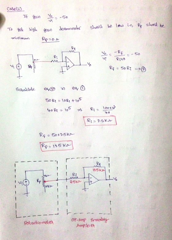
2, Design a variable gain amplifier using an inverting circuit and a 10 ΚΩ potentiometer. It...
P3. Using the circuit below to design the inverting amplifier having a gain of -10 and...
 P3. Using the circuit below to design the inverting amplifier having a gain of -10 and input resistance of 100 kΩ. Give the values of R1. 2 do
15. Design an inverting amplifier to have a gain of 20 using the MCP6021 and a...
15. Design an inverting amplifier to have a gain of 20 using the MCP6021 and a single +5 V supply. What will be the typical 3-dB bandwidth of the amplifier?
Design an inverting amplifier to have a gain of 20 using the LMV358 and a single...
Design an inverting amplifier to have a gain of 20 using the LMV358 and a single +5 V supply. What will be the typical 3-dB bandwidth of the amplifier? AND Compare the typical (a) gain bandwidth product and (b) slew rate of the LMV358 and the LM358?
5.8 a) Design an inverting amplifier with a gain of 4. Use an ideal op amp,...
5.8 a) Design an inverting amplifier with a gain of 4. Use an ideal op amp, a resistor in the feedback path, and 12 V power supplies. b) Using your design from part (a), determine the range of input voltages that will keep the op amp in its linear operating region. c) Suppose you wish to amplify a 2 V signal, using your design from part (a) with a variable feedback resistor. What is the largest value of feedback resistance...
2. Design a non-inverting op-amp circuit with two resistors under the following conditions: a. The gain of the ampl...
 2. Design a non-inverting op-amp circuit with two resistors under the following conditions: a. The gain of the amplifier must be +10 b. The input range is ± 2V c. The total power consumed by the resistors must be less than 100 mW Show all the calculations required to design the amplifier circuit with the shown specifications.in details Use MULTISIM to create the op-amp circuit and print a fully labelled diagram of the circuits with the voltmeters displays showing both...
Design a difference amplifier circuit to yield a variable differential gain
Design a difference amplifier circuit to yield a variable differential gain in the range 1 to 100 and utilizing a 100 kΩ variable resistor. The design should include an ideal op-amp (Hint: Design the second stage for a gain of 0.5).
Assuming an ideal op-amp, design an inverting amplifier with a gain of 26 dB
Assuming an ideal op-amp, design an inverting amplifier with a gain of 26 dB having the largest possible R1 value under the constraint of having to use resistors no larger than 1 MΩ. If the input voltage source of this amplifier has an internal resistance r0 = 50 kΩ, how will this affect the gain? Design a solution that will eliminate the effect of the internal source resistance without having to change the values of R1 and R2.
The circuit of Fig. 5.Sa is to be used as an inverting amplifier with a gain...
 The circuit of Fig. 5.Sa is to be used as an inverting amplifier with a gain of 10 VIV and is to employ the HA741C op amp. Specify suitable component values to ensure a maximum output error of 10 mV with minimum power dissipation in the resistors. Rt 0 FIGURE $.S
please answer 3rd question using multisim 2-Design an inverting amplifier with a gain of -100 at...
 please answer 3rd question using multisim
2-Design an inverting amplifier with a gain of -100 at 100Hz. Increase the amplitude of the input signal until you observe clipping. Continue increasing the amplitude and observe the results. Briefly explain and comment your results 3-For the same amplifier as 2, increase the frequency of the input signal until you observe the slew rate characteristic associated with the Op Amp. Try different amplitudes Briefly explain and comment your results. 4- For the same...
please answer 3rd question using multisim
2-Design an inverting amplifier with a gain of -100 at 100Hz. Increase the amplitude of the input signal until you observe clipping. Continue increasing the amplitude and observe the results. Briefly explain and comment your results 3-For the same amplifier as 2, increase the frequency of the input signal until you observe the slew rate characteristic associated with the Op Amp. Try different amplitudes Briefly explain and comment your results. 4- For the same...
A. Design one circuit: Including power supply values and connections. 1-Design a non-inverting am...
A. Design one circuit: Including power supply values and connections. 1-Design a non-inverting amplifier with a gain of +11 V/V (+/- 10%) with an input of 0.5 V sin(2pi 200t). 2-Design an inverting amplifier with a gain of -22 V/V (+/- 10%) with an input of 0.12 V sin(2pi500t) 3-Design a 555 time astable with a 1 Hz output to an LED load 4-Design a single stage low-pass filter with a cutoff frequency of 300 Hz.
 P3. Using the circuit below to design the inverting amplifier having a gain of -10 and input resistance of 100 kΩ. Give the values of R1. 2 do
 2. Design a non-inverting op-amp circuit with two resistors under the following conditions: a. The gain of the amplifier must be +10 b. The input range is ± 2V c. The total power consumed by the resistors must be less than 100 mW Show all the calculations required to design the amplifier circuit with the shown specifications.in details Use MULTISIM to create the op-amp circuit and print a fully labelled diagram of the circuits with the voltmeters displays showing both...
 The circuit of Fig. 5.Sa is to be used as an inverting amplifier with a gain of 10 VIV and is to employ the HA741C op amp. Specify suitable component values to ensure a maximum output error of 10 mV with minimum power dissipation in the resistors. Rt 0 FIGURE $.S
 please answer 3rd question using multisim
2-Design an inverting amplifier with a gain of -100 at 100Hz. Increase the amplitude of the input signal until you observe clipping. Continue increasing the amplitude and observe the results. Briefly explain and comment your results 3-For the same amplifier as 2, increase the frequency of the input signal until you observe the slew rate characteristic associated with the Op Amp. Try different amplitudes Briefly explain and comment your results. 4- For the same...
please answer 3rd question using multisim
2-Design an inverting amplifier with a gain of -100 at 100Hz. Increase the amplitude of the input signal until you observe clipping. Continue increasing the amplitude and observe the results. Briefly explain and comment your results 3-For the same amplifier as 2, increase the frequency of the input signal until you observe the slew rate characteristic associated with the Op Amp. Try different amplitudes Briefly explain and comment your results. 4- For the same...
Most questions answered within 3 hours.
-
Where is the error in this code sequence?
String s1 = "Hello";
String s2 = "ello";...
asked 10 months ago -
Financial data for Joel de Paris, Inc., for last year
follow:
Joel de Paris, Inc.
Balance...
asked 10 months ago -
Consider this reaction:
Al2(SO4)3 (aq)+ BaCl3
(aq) Al2Cl6 (aq)- +
3BaSO4(s) . What is the...
asked 10 months ago -
Suppose that Savneet is considering increasing her
recent random sample from 20 car rentals to 40...
asked 10 months ago -
Trucks arrive at an unloading terminal at an average rate of 120
per hour.
Trucks arrive...
asked 10 months ago -
Why are methanol and ethanol completely soluble in water while
octanol is not very little soluble....
asked 10 months ago -
A facilities manager at a university reads in a research report
that the mean amount of...
asked 10 months ago -
When the CuSO4 is rehydrated by adding water to the anhydrous
compound, is this an endothermic...
asked 10 months ago -
A ray of sunlight is passing from diamond into crown glass; the
angle of incidence is...
asked 10 months ago -
A block of mass 0.249 kg is placed on top of a light, vertical
spring of...
asked 10 months ago -
how do the kidneys compensate in the presences of acidosis
a) trigger hyperventilate
b) reserve acid...
asked 10 months ago -
Question 501 pts
The rental rate of capital to the firm increases. Which of the
following...
asked 10 months ago