
Homework Answers


Add Answer to:
Question 2: For the connection shown in Figure determine whether the bolts are adequate to support...
Chapter 4, Reserve Problem 018 Three bolts are used in the connection shown in the figure....
 Chapter 4, Reserve Problem 018 Three bolts are used in the connection shown in the figure. The thickness of plate (1) is 20 mm. The ultimate shear strength of the bolts is 385 MPa, and the ultimate bearing strength of plate (1) is 385 MPa. Determine the minimum bolt diameter required to support an applied load of P = 180 KN if a minimum factor of safety of 2.5 is required with respect to both bolt shear and plate bearing...
ein (2) Three identical bolts are used in the connection shown and the thickness of the...
 ein (2) Three identical bolts are used in the connection shown and the thickness of the center plate is t = 18 mm. The ultimate shear stress in the bolts is 320 MPa and the ultimate bearing stress in the plate is 350 MPa. Determine the minimum bolt diameter required to support an applied load of P= 180 kN for a factor of safety of 2.5. Ans: 23.8 mm Р
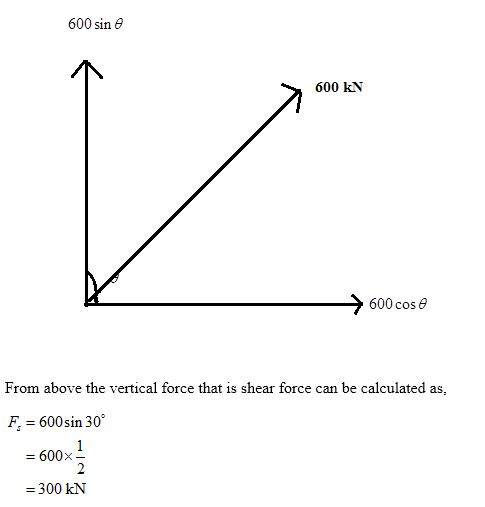
follow australian codes (a) The rigid bolted connection shown in Figure 4 is used to transmit a total vertical load...
 follow australian codes
(a) The rigid bolted connection shown in Figure 4 is used to transmit a total vertical load of 350 kN applied as shown. Two bracket plates are connected to the flanges of the I section using the bolt groups (refer figure 4) and hence, the bolts are loaded in- plane. Determine if the bolted connection shown in Figure 4 can safely support the applied load (use cl. 9.4.1 AS4100 1998). The bolts are M20 of 8.8S grade...
follow australian codes
(a) The rigid bolted connection shown in Figure 4 is used to transmit a total vertical load of 350 kN applied as shown. Two bracket plates are connected to the flanges of the I section using the bolt groups (refer figure 4) and hence, the bolts are loaded in- plane. Determine if the bolted connection shown in Figure 4 can safely support the applied load (use cl. 9.4.1 AS4100 1998). The bolts are M20 of 8.8S grade...
5. The figure shows a cast-iron bearing block that is to be bolted to a steel ceiling joist and is to support a gravity load of 18 kN. Bolts used are M24 ISO 8.8 with coarse threads. The joist fl...
 5. The figure shows a cast-iron bearing block that is to be bolted to a steel ceiling joist and is to support a gravity load of 18 kN. Bolts used are M24 ISO 8.8 with coarse threads. The joist flanges are 20 mm in thickness, and the dimension A is 20 mm. The modulus of elasticity of the block is 135 G Pa. Find the safe tensile shear load F that can be applied to this connection to provide a...
b) Two Grade 8.8 M20X bolts in standard holes are in a connection as shown Considering...
 b) Two Grade 8.8 M20X bolts in standard holes are in a connection as shown Considering bolt strength only, what force. E, can be applied according to NZS3404 before it is considered that the following could occur: (0) slin (ii) bolt shear strength. (3) c) If the bearing check at a beam end support fails, what are two things that can be done to allow the same beam to be used satisfying NZS3404?
3. All bolts in the seismic bracing connection shown in the figure are Grade A490, 34-nch-diameter...
 3. All bolts in the seismic bracing connection shown in the figure are Grade A490, 34-nch-diameter bolts (8 bol Its total) The bolts are bearing-type in standard holes, and the threads are excluded from the shear planes The seismic bracing is subject to a 200-kip tension force that passed through the center of gravity of the boltu group. Check the adequacy of the bolts P,1-200 k
The joint shown in Figure 1 is made from steel Grade 350 (AS/NZS 3678). Four bolts...
 The joint shown in Figure 1 is made from steel Grade 350 (AS/NZS
3678). Four bolts are used. Diameters of all holes are 5 mm. Note
that the middle hole on both Plates A is just a hole with no bolt.
The shear design capacity (reduced nominal capacity) of the bolts
in single shear is 10 kN. Dimensions given below are in
mm.
Determinre the maximum tension design force:
a) * N2PlatesA that the double plate A can support.
b)...
The joint shown in Figure 1 is made from steel Grade 350 (AS/NZS
3678). Four bolts are used. Diameters of all holes are 5 mm. Note
that the middle hole on both Plates A is just a hole with no bolt.
The shear design capacity (reduced nominal capacity) of the bolts
in single shear is 10 kN. Dimensions given below are in
mm.
Determinre the maximum tension design force:
a) * N2PlatesA that the double plate A can support.
b)...
The figure shows a bolted lap joint that uses SAE grade 5 bolts. The members are...
 The figure shows a bolted lap joint that uses SAE grade 5 bolts. The members are made of cold- drawn AISI 1020 steel. Assume the bolt threads do not extend into the joint. Find the safe tensile shear load F that can be applied to this connection to provide a minimum factor of safety of 2 for the following failure modes: shear of bolts, bearing on bolts, bearing on members, and tension of members Problem 8-66 in in-20 UNC in...
stion No:3 (30 pts) Assume any missing data, use only LRDF method For the connection shown...
 stion No:3 (30 pts) Assume any missing data, use only LRDF method For the connection shown in Figure 3, both the plate and the angle are made of ASTM A992. The steel angel is L6x6x3/8 and the plate is 5/16" thick. The bolts are /STM Л325 and they are " diameter standard holes bcaring type connection. Determine the followings: (a) The capacity of the connection considering 11/4 in. 3 in. 3 in. 3 in. only the shear strength of the...
Figure 1 shows a bolted truss connection used in the construction of a roof system for...
 Figure 1 shows a bolted truss connection used in the construction of a roof system for a large industrial building. The diagonal members of the truss are 150 x 150 x 12 Equal Angies (Grade 300). They are bolted to a 16 mm gusset plate using 8 M20 Grade 8.8/S bolts. a) What is the axial tension design capacity of the connection? (Assume that the 16 mm gusset plate is the strongest component and will not fail) (12 Marks) b)...
 Chapter 4, Reserve Problem 018 Three bolts are used in the connection shown in the figure. The thickness of plate (1) is 20 mm. The ultimate shear strength of the bolts is 385 MPa, and the ultimate bearing strength of plate (1) is 385 MPa. Determine the minimum bolt diameter required to support an applied load of P = 180 KN if a minimum factor of safety of 2.5 is required with respect to both bolt shear and plate bearing...
 ein (2) Three identical bolts are used in the connection shown and the thickness of the center plate is t = 18 mm. The ultimate shear stress in the bolts is 320 MPa and the ultimate bearing stress in the plate is 350 MPa. Determine the minimum bolt diameter required to support an applied load of P= 180 kN for a factor of safety of 2.5. Ans: 23.8 mm Р
 follow australian codes
(a) The rigid bolted connection shown in Figure 4 is used to transmit a total vertical load of 350 kN applied as shown. Two bracket plates are connected to the flanges of the I section using the bolt groups (refer figure 4) and hence, the bolts are loaded in- plane. Determine if the bolted connection shown in Figure 4 can safely support the applied load (use cl. 9.4.1 AS4100 1998). The bolts are M20 of 8.8S grade...
follow australian codes
(a) The rigid bolted connection shown in Figure 4 is used to transmit a total vertical load of 350 kN applied as shown. Two bracket plates are connected to the flanges of the I section using the bolt groups (refer figure 4) and hence, the bolts are loaded in- plane. Determine if the bolted connection shown in Figure 4 can safely support the applied load (use cl. 9.4.1 AS4100 1998). The bolts are M20 of 8.8S grade...
 5. The figure shows a cast-iron bearing block that is to be bolted to a steel ceiling joist and is to support a gravity load of 18 kN. Bolts used are M24 ISO 8.8 with coarse threads. The joist flanges are 20 mm in thickness, and the dimension A is 20 mm. The modulus of elasticity of the block is 135 G Pa. Find the safe tensile shear load F that can be applied to this connection to provide a...
 b) Two Grade 8.8 M20X bolts in standard holes are in a connection as shown Considering bolt strength only, what force. E, can be applied according to NZS3404 before it is considered that the following could occur: (0) slin (ii) bolt shear strength. (3) c) If the bearing check at a beam end support fails, what are two things that can be done to allow the same beam to be used satisfying NZS3404?
 3. All bolts in the seismic bracing connection shown in the figure are Grade A490, 34-nch-diameter bolts (8 bol Its total) The bolts are bearing-type in standard holes, and the threads are excluded from the shear planes The seismic bracing is subject to a 200-kip tension force that passed through the center of gravity of the boltu group. Check the adequacy of the bolts P,1-200 k
 The joint shown in Figure 1 is made from steel Grade 350 (AS/NZS
3678). Four bolts are used. Diameters of all holes are 5 mm. Note
that the middle hole on both Plates A is just a hole with no bolt.
The shear design capacity (reduced nominal capacity) of the bolts
in single shear is 10 kN. Dimensions given below are in
mm.
Determinre the maximum tension design force:
a) * N2PlatesA that the double plate A can support.
b)...
The joint shown in Figure 1 is made from steel Grade 350 (AS/NZS
3678). Four bolts are used. Diameters of all holes are 5 mm. Note
that the middle hole on both Plates A is just a hole with no bolt.
The shear design capacity (reduced nominal capacity) of the bolts
in single shear is 10 kN. Dimensions given below are in
mm.
Determinre the maximum tension design force:
a) * N2PlatesA that the double plate A can support.
b)...
 The figure shows a bolted lap joint that uses SAE grade 5 bolts. The members are made of cold- drawn AISI 1020 steel. Assume the bolt threads do not extend into the joint. Find the safe tensile shear load F that can be applied to this connection to provide a minimum factor of safety of 2 for the following failure modes: shear of bolts, bearing on bolts, bearing on members, and tension of members Problem 8-66 in in-20 UNC in...
 stion No:3 (30 pts) Assume any missing data, use only LRDF method For the connection shown in Figure 3, both the plate and the angle are made of ASTM A992. The steel angel is L6x6x3/8 and the plate is 5/16" thick. The bolts are /STM Л325 and they are " diameter standard holes bcaring type connection. Determine the followings: (a) The capacity of the connection considering 11/4 in. 3 in. 3 in. 3 in. only the shear strength of the...
 Figure 1 shows a bolted truss connection used in the construction of a roof system for a large industrial building. The diagonal members of the truss are 150 x 150 x 12 Equal Angies (Grade 300). They are bolted to a 16 mm gusset plate using 8 M20 Grade 8.8/S bolts. a) What is the axial tension design capacity of the connection? (Assume that the 16 mm gusset plate is the strongest component and will not fail) (12 Marks) b)...
Most questions answered within 3 hours.
-
Where is the error in this code sequence?
String s1 = "Hello";
String s2 = "ello";...
asked 10 months ago -
Financial data for Joel de Paris, Inc., for last year
follow:
Joel de Paris, Inc.
Balance...
asked 10 months ago -
Consider this reaction:
Al2(SO4)3 (aq)+ BaCl3
(aq) Al2Cl6 (aq)- +
3BaSO4(s) . What is the...
asked 10 months ago -
Suppose that Savneet is considering increasing her
recent random sample from 20 car rentals to 40...
asked 10 months ago -
Trucks arrive at an unloading terminal at an average rate of 120
per hour.
Trucks arrive...
asked 10 months ago -
Why are methanol and ethanol completely soluble in water while
octanol is not very little soluble....
asked 10 months ago -
A facilities manager at a university reads in a research report
that the mean amount of...
asked 10 months ago -
When the CuSO4 is rehydrated by adding water to the anhydrous
compound, is this an endothermic...
asked 10 months ago -
A ray of sunlight is passing from diamond into crown glass; the
angle of incidence is...
asked 10 months ago -
A block of mass 0.249 kg is placed on top of a light, vertical
spring of...
asked 10 months ago -
how do the kidneys compensate in the presences of acidosis
a) trigger hyperventilate
b) reserve acid...
asked 10 months ago -
Question 501 pts
The rental rate of capital to the firm increases. Which of the
following...
asked 10 months ago