
E7.1

E7.2

Exercise E7.1-Passive Low Pass Filter 1. Measure the 1 kΩ resistor and the l μ F capacitor using the DMM. Enter these values below Measured value of i kΩ resistor- a .goL Measured value of 1 F capacitor O.a 2. Construct the low pass fiter circuit ilustrated in Figure E7.1 E7-1 Figure E7.1. The Passive Low Pass Filter Circuit.
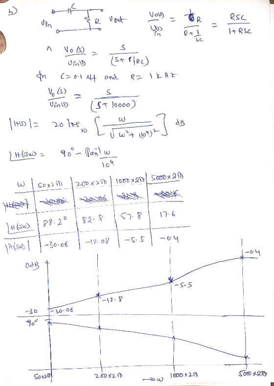
Exercise E72-Passive High Pass Filter 1. Measure the l kΩ resistor and the 0.1 μ F capacitor using the DMM. Enter these values below. Measured value of İ k Ω resistor- o- Measured value of 0.1 μF capacitor =-o-sr- 2. Construct the high pass fiter circuit illustrated in Figure ET Figure E7 2. The Passive High Pass Filter Circuit
Homework Answers

Add Answer to:
EE 3342 Pre-Lab Exercises for Experiment 7: Passive Analog Filters Read the handout for Experimen...
1. Read the laboratory supplement entitled “Frequency Response". 2. Read the remainder of this handout. 3....
 1. Read the laboratory supplement entitled “Frequency Response". 2. Read the remainder of this handout. 3. In Multisim, build the circuit shown in Figure 1 with C=0.22 uF and R = 2.2 k12. This circuit looks like a simple voltage divider except that one of the resistors is replaced by a capacitor. Il Figure 1: RC network. F Set up Vin to be a 1 Vpp sinusoid with 0 VDC Offset using a function generator. 2. Connect the oscilloscope in...
2. supplies for operation. Unlike passive filters, the gains of active filters ean be varied te...
 2. supplies for operation. Unlike passive filters, the gains of active filters ean be varied te desirable values Active filters contain active devices (amplifiers) that require de power Using RC op-amp circuit (see Figure 2.3 low pass filter, formed from single-time constant circuit. Note: Op-amp requires 2-de power supplies. Y.-W andV- a. Determine the transfer function T(s)-Vo (s)Vi(s) b. From (a) what is the low frequency gain, and the 3 db frequency Use (b) to design low pass filter such...
Learning Goal: To analyze and design a passive, first-order low- pass filter using a series RL...
 Learning Goal: To analyze and design a passive, first-order low- pass filter using a series RL circuit. The analysis and design will be repeated for a series RC circuit. An electrocardiogram needs to detect periodic signals of approximately 1 Hz (since the resting heart rate of a healthy adult is between 55 and 70 beats per minute). The instrument operates in an electrical environment that is very noisy with a frequency of 60 Hz. It is desirable to have a...
What is the answer to question 23.1? 23.1 Active low-pass filter You can make a low-pass...
 What is the answer to question
23.1?
23.1 Active low-pass filter You can make a low-pass filter by putting a capacitor Cr and resistor Rf in parallel for Zj as shown in Figure 23.1. At low frequencies (well below the corner frequency), the feedback impedance is approximately Rf and the gain of a non-inverting amplifier is is 1 +R//R,. At high frequencies (well above the corner frequency),the impedance is approx- imately 1/(jwCs), and the gain of a non-inverting amplifier is...
What is the answer to question
23.1?
23.1 Active low-pass filter You can make a low-pass filter by putting a capacitor Cr and resistor Rf in parallel for Zj as shown in Figure 23.1. At low frequencies (well below the corner frequency), the feedback impedance is approximately Rf and the gain of a non-inverting amplifier is is 1 +R//R,. At high frequencies (well above the corner frequency),the impedance is approx- imately 1/(jwCs), and the gain of a non-inverting amplifier is...
Learning Goal: To analyze and design a passive, first-order low-pass filter using a series RL circuit....
 Learning Goal: To analyze and design a passive, first-order low-pass filter using a series RL circuit. The analysis and design will be repeated for a series RC circuit. An electrocardiogram needs to detect periodic signals of approximately 1 Hz (since the resting heart rate of a healthy adult is between 55 and 70 beats per minute). The instrument operates in an electrical environment that is very noisy with a frequency of 60 Hz. It is desirable to have a low-pass...
Resistors 2700 3300 3900 4700 56002 Capacitors 1.OnF 1.5nF 2.2nF Inductors 2.7mH 1500 1800 2200 6800...
 Resistors 2700 3300 3900 4700 56002 Capacitors 1.OnF 1.5nF 2.2nF Inductors 2.7mH 1500 1800 2200 6800 8200 1.0kn 1.2k2 1.5k 1.8k 22.2k02 2.7k 2 3.3nF 4.7nF 6.8nF 3.3k 3.9k 4.7kn 5.6k 26.8k0 8.2k210k 2 12kΩ 10nF 15F 22nF 15kΩ 18kQ2 22kΩ 27kg 33kg 39k 47kg 56kΩ 33nF 47nF 68nF 68k 82kg 100k 120ko 150k 150k 180k 220ko 100nF 150nF 270kn 330kn 390kW 470kn 560kn 680k0 820ko 1.0M Table 1 In this lab, you will design and build Passive & Active...
Analyals and Deaign of High-Pass Filters O 5o 14 > I Review I Corstante Learning Goal:...
 Analyals and Deaign of High-Pass Filters O 5o 14 > I Review I Corstante Learning Goal: To analyze and design a passive, first-order high-pass titer using a series RC arcuit. • Part A-Qualtative analysis of a series RC low-pess fiher An instrument nceds to detect penodio signals ot approximately 5O00 Hz. The instrument operates in an environment with a lot ot periodic noise ranging trom a few to several hundrod hertz. Ahigh-pass RC titer can be bult using avalable 2.5...
Notes you have to use MathLab No Hand Writing and Write answer by typing PDF Or document word.
 Notes you have to use
MathLab
No Hand Writing
and Write answer by typing
PDF Or document word.
Active 1st Order Filters Objective An active filter is a type of analog electronic filter distinguished by the use of one or more active components. Typically this will be a yacuum tube, or solid-state Active filters have three main advantages over passive filters: Inductors can be avoided. Passive filters without inductors cannot obtain a high Q (low damping), but with them are...
Notes you have to use
MathLab
No Hand Writing
and Write answer by typing
PDF Or document word.
Active 1st Order Filters Objective An active filter is a type of analog electronic filter distinguished by the use of one or more active components. Typically this will be a yacuum tube, or solid-state Active filters have three main advantages over passive filters: Inductors can be avoided. Passive filters without inductors cannot obtain a high Q (low damping), but with them are...
Active filters contain active devices (amplifiers) that require de power supplies for operation. Unlike passive filters,...
 Active filters contain active devices (amplifiers) that require de power supplies for operation. Unlike passive filters, the gains of active filters can be varied to desirable values. 2. Using RC op-amp circuit (see Figure 2.3 low pass filter, formed from single-time constant circuit. Note: Op-amp requires 2-de power supplies. Vee 4V and Vee=-4V Determine the transfer function T(s) = Vo (s)/Vi(s) Determine: low frequency gain, K and 3-db frequency in Hz if R1 = 1 KM, R2 =8 KO, and...
checking to see if the answers i got are correct and help with the other parts....
 checking to see if the answers i got are correct and help with
the other parts. thank you
Chapter 26 Laboratory Application Assignment In this lab application assignment you will examine an RC coupling circuit and an RC low-pass filter. In the RC coulina circuit you will see how the series capacitor blocks the de component of the input voltage but passes the ac component. In the RC low-pass filter you will see how the low frequencies are passed from...
checking to see if the answers i got are correct and help with
the other parts. thank you
Chapter 26 Laboratory Application Assignment In this lab application assignment you will examine an RC coupling circuit and an RC low-pass filter. In the RC coulina circuit you will see how the series capacitor blocks the de component of the input voltage but passes the ac component. In the RC low-pass filter you will see how the low frequencies are passed from...
 1. Read the laboratory supplement entitled “Frequency Response". 2. Read the remainder of this handout. 3. In Multisim, build the circuit shown in Figure 1 with C=0.22 uF and R = 2.2 k12. This circuit looks like a simple voltage divider except that one of the resistors is replaced by a capacitor. Il Figure 1: RC network. F Set up Vin to be a 1 Vpp sinusoid with 0 VDC Offset using a function generator. 2. Connect the oscilloscope in...
 2. supplies for operation. Unlike passive filters, the gains of active filters ean be varied te desirable values Active filters contain active devices (amplifiers) that require de power Using RC op-amp circuit (see Figure 2.3 low pass filter, formed from single-time constant circuit. Note: Op-amp requires 2-de power supplies. Y.-W andV- a. Determine the transfer function T(s)-Vo (s)Vi(s) b. From (a) what is the low frequency gain, and the 3 db frequency Use (b) to design low pass filter such...
 Learning Goal: To analyze and design a passive, first-order low- pass filter using a series RL circuit. The analysis and design will be repeated for a series RC circuit. An electrocardiogram needs to detect periodic signals of approximately 1 Hz (since the resting heart rate of a healthy adult is between 55 and 70 beats per minute). The instrument operates in an electrical environment that is very noisy with a frequency of 60 Hz. It is desirable to have a...
 What is the answer to question
23.1?
23.1 Active low-pass filter You can make a low-pass filter by putting a capacitor Cr and resistor Rf in parallel for Zj as shown in Figure 23.1. At low frequencies (well below the corner frequency), the feedback impedance is approximately Rf and the gain of a non-inverting amplifier is is 1 +R//R,. At high frequencies (well above the corner frequency),the impedance is approx- imately 1/(jwCs), and the gain of a non-inverting amplifier is...
What is the answer to question
23.1?
23.1 Active low-pass filter You can make a low-pass filter by putting a capacitor Cr and resistor Rf in parallel for Zj as shown in Figure 23.1. At low frequencies (well below the corner frequency), the feedback impedance is approximately Rf and the gain of a non-inverting amplifier is is 1 +R//R,. At high frequencies (well above the corner frequency),the impedance is approx- imately 1/(jwCs), and the gain of a non-inverting amplifier is...
 Learning Goal: To analyze and design a passive, first-order low-pass filter using a series RL circuit. The analysis and design will be repeated for a series RC circuit. An electrocardiogram needs to detect periodic signals of approximately 1 Hz (since the resting heart rate of a healthy adult is between 55 and 70 beats per minute). The instrument operates in an electrical environment that is very noisy with a frequency of 60 Hz. It is desirable to have a low-pass...
 Resistors 2700 3300 3900 4700 56002 Capacitors 1.OnF 1.5nF 2.2nF Inductors 2.7mH 1500 1800 2200 6800 8200 1.0kn 1.2k2 1.5k 1.8k 22.2k02 2.7k 2 3.3nF 4.7nF 6.8nF 3.3k 3.9k 4.7kn 5.6k 26.8k0 8.2k210k 2 12kΩ 10nF 15F 22nF 15kΩ 18kQ2 22kΩ 27kg 33kg 39k 47kg 56kΩ 33nF 47nF 68nF 68k 82kg 100k 120ko 150k 150k 180k 220ko 100nF 150nF 270kn 330kn 390kW 470kn 560kn 680k0 820ko 1.0M Table 1 In this lab, you will design and build Passive & Active...
 Analyals and Deaign of High-Pass Filters O 5o 14 > I Review I Corstante Learning Goal: To analyze and design a passive, first-order high-pass titer using a series RC arcuit. • Part A-Qualtative analysis of a series RC low-pess fiher An instrument nceds to detect penodio signals ot approximately 5O00 Hz. The instrument operates in an environment with a lot ot periodic noise ranging trom a few to several hundrod hertz. Ahigh-pass RC titer can be bult using avalable 2.5...
 Notes you have to use
MathLab
No Hand Writing
and Write answer by typing
PDF Or document word.
Active 1st Order Filters Objective An active filter is a type of analog electronic filter distinguished by the use of one or more active components. Typically this will be a yacuum tube, or solid-state Active filters have three main advantages over passive filters: Inductors can be avoided. Passive filters without inductors cannot obtain a high Q (low damping), but with them are...
Notes you have to use
MathLab
No Hand Writing
and Write answer by typing
PDF Or document word.
Active 1st Order Filters Objective An active filter is a type of analog electronic filter distinguished by the use of one or more active components. Typically this will be a yacuum tube, or solid-state Active filters have three main advantages over passive filters: Inductors can be avoided. Passive filters without inductors cannot obtain a high Q (low damping), but with them are...
 Active filters contain active devices (amplifiers) that require de power supplies for operation. Unlike passive filters, the gains of active filters can be varied to desirable values. 2. Using RC op-amp circuit (see Figure 2.3 low pass filter, formed from single-time constant circuit. Note: Op-amp requires 2-de power supplies. Vee 4V and Vee=-4V Determine the transfer function T(s) = Vo (s)/Vi(s) Determine: low frequency gain, K and 3-db frequency in Hz if R1 = 1 KM, R2 =8 KO, and...
 checking to see if the answers i got are correct and help with
the other parts. thank you
Chapter 26 Laboratory Application Assignment In this lab application assignment you will examine an RC coupling circuit and an RC low-pass filter. In the RC coulina circuit you will see how the series capacitor blocks the de component of the input voltage but passes the ac component. In the RC low-pass filter you will see how the low frequencies are passed from...
checking to see if the answers i got are correct and help with
the other parts. thank you
Chapter 26 Laboratory Application Assignment In this lab application assignment you will examine an RC coupling circuit and an RC low-pass filter. In the RC coulina circuit you will see how the series capacitor blocks the de component of the input voltage but passes the ac component. In the RC low-pass filter you will see how the low frequencies are passed from...
Most questions answered within 3 hours.
-
Where is the error in this code sequence?
String s1 = "Hello";
String s2 = "ello";...
asked 10 months ago -
Financial data for Joel de Paris, Inc., for last year
follow:
Joel de Paris, Inc.
Balance...
asked 10 months ago -
Consider this reaction:
Al2(SO4)3 (aq)+ BaCl3
(aq) Al2Cl6 (aq)- +
3BaSO4(s) . What is the...
asked 10 months ago -
Suppose that Savneet is considering increasing her
recent random sample from 20 car rentals to 40...
asked 10 months ago -
Trucks arrive at an unloading terminal at an average rate of 120
per hour.
Trucks arrive...
asked 10 months ago -
Why are methanol and ethanol completely soluble in water while
octanol is not very little soluble....
asked 10 months ago -
A facilities manager at a university reads in a research report
that the mean amount of...
asked 10 months ago -
When the CuSO4 is rehydrated by adding water to the anhydrous
compound, is this an endothermic...
asked 10 months ago -
A ray of sunlight is passing from diamond into crown glass; the
angle of incidence is...
asked 10 months ago -
A block of mass 0.249 kg is placed on top of a light, vertical
spring of...
asked 10 months ago -
how do the kidneys compensate in the presences of acidosis
a) trigger hyperventilate
b) reserve acid...
asked 10 months ago -
Question 501 pts
The rental rate of capital to the firm increases. Which of the
following...
asked 10 months ago