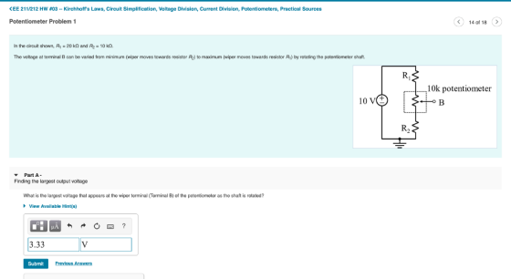
In the circuit shown, R₁ = 20 kΩ and R₂ = 10 kΩ.
The voltage at terminal B can be varied from minimum (wiper moves towards resistor R₂) to maximum (wiper moves towards resistor R₁) by rotating the potentiometer shaft.


Homework Answers


In the circuit shown, R₁ and R₂ has not yet been determined.
 In the circuit shown, R₁ and R₂ has not yet been determined. The voltage at terminal B(VB) can be varied from minimum (wiper moves towards resistor R₂) to maximum (wiper moves towards resistor R₁) by rotating the potentiometer shaft Part A- Finding the resistor values to get desired voltage swing Determine the value of R₁ (in kΩ) needed to get a voltage swing of 2V ≤Vs≤7V.Part B- Finding the resistor values to get desired voltage swing. Determine the value of R₂ (in kΩ) needed...
please kindly do all question please 1) A Megohmmeter is an instrument for measuring very high...
please kindly do all question please 1) A Megohmmeter is an instrument for measuring very high resistance levels. True or False 2) A ladder network is a cascaded set of series-parallel combinations that has the appearance of a ladder. True or False 3) A transistor is a series-parallel circuit comprised of three variable resistors. true or false 4) A transistor is a three terminal semiconductor electronic device that can be used for amplification and switching purposes. true or false 5) An ammeter...
04) The RC Circuit shown below includes both a fixed resistor and a potentiometer. By turning...
 04) The RC Circuit shown below includes both a fixed resistor and a potentiometer. By turning the knob on the potentiometer, the resistance between the fixed resistor and the capacitor can be changed within the range of 0 to 20 ko. a. Is this a lowpass or high pass configuration? R = 10 kn Rror = 20 k2 C = 10 uF b. Find an expression for the voltage across the capacitor Vou(t) to a unit voltage step (the voltage...
Question 4 (8%) The potentiometer circuit shown in Fig. 3 is used to measure angular position 0. The capacitor C is use...
 Question 4 (8%) The potentiometer circuit shown in Fig. 3 is used to measure angular position 0. The capacitor C is used to reduce contact bounce, and the op-amp isolates the potentiometer from long lead wires and recording instrument resistance loading. The potentiometer being used rotate 320 degrees has a resistance Rp 4.0k2, and is capable of dissipating 0.02W of power in most environments. The circuit is to have a minimum sensitivity of 10.0mV/degree when 100m of AWG28 copper lead...
For the circuit shown below, calculate the voltage, current, and power associated with the 2.7 kΩ...
 For the circuit shown below, calculate the voltage, current, and
power associated with the 2.7 kΩ resistor. Use four decimal places
in your calculation.
R. 6.3 k 1 R 1.1 k R2 4.75 V 2.7 k R. 870 4
For the circuit shown below, calculate the voltage, current, and
power associated with the 2.7 kΩ resistor. Use four decimal places
in your calculation.
R. 6.3 k 1 R 1.1 k R2 4.75 V 2.7 k R. 870 4
Find the maximum power transferred to resistor R in the circuit below. 22 kΩ 100V(±) 40...
 Find the maximum power transferred to resistor R in the circuit below. 22 kΩ 100V(±) 40 kΩ 30 kΩ ら
1 ) A series circuit consisted of R= 10 KΩ, L= 42 mH , C= 2.1...
 1 ) A series circuit consisted of R= 10 KΩ, L= 42 mH , C= 2.1 µF
is connected to an alternative voltage with maximum voltage of
Vm = 24 V and frequency of 300.0 Hz.
Find the following:
Show the formula for each question. Show your
Calculations – put result in a box with its unit. Please write your
answer under each question
a)Find the value of angular frequency ω .
b) Inductive Reactance ( XL)
c)Capacitive Reactance (...
1 ) A series circuit consisted of R= 10 KΩ, L= 42 mH , C= 2.1 µF
is connected to an alternative voltage with maximum voltage of
Vm = 24 V and frequency of 300.0 Hz.
Find the following:
Show the formula for each question. Show your
Calculations – put result in a box with its unit. Please write your
answer under each question
a)Find the value of angular frequency ω .
b) Inductive Reactance ( XL)
c)Capacitive Reactance (...
This circuit is a Wheatstone Bridge. It is used for numerous scientific and engineering applications. Here,...
 This circuit is a Wheatstone Bridge. It is used for numerous
scientific and engineering applications. Here, R1 = 20 kΩ, R2 = 10
kΩ, R3 = 5 kΩ, and R4 = 10 kΩ. ε = 5 V.
a) Determine the Thevenin equivalent resistance RTH between
points A and B. (Hint: when we remove the power supply and short
the circuit, the wire connecting the “top” and “bottom” of the
bridge can then be drawn to go right down the center...
This circuit is a Wheatstone Bridge. It is used for numerous
scientific and engineering applications. Here, R1 = 20 kΩ, R2 = 10
kΩ, R3 = 5 kΩ, and R4 = 10 kΩ. ε = 5 V.
a) Determine the Thevenin equivalent resistance RTH between
points A and B. (Hint: when we remove the power supply and short
the circuit, the wire connecting the “top” and “bottom” of the
bridge can then be drawn to go right down the center...
Consider the circuit of Figure 6.19. The AC supply has a peak voltage of 10 V...
 Consider the circuit of Figure 6.19. The AC supply has a peak
voltage of 10 V and a frequency of 1 kHz. The resistor has a value
of 1 k2, and the capacitor has a capacitance of 0.1 F.
a. find the Thevenin equivalent circuit
b. If we varied the frequency of the source, at what frequency
would the impedence be:
i. Maximum
ii. Minimum
iii. What are the impedences for cases 9(b)i and 9(b)ii ?
c. Now we connect...
Consider the circuit of Figure 6.19. The AC supply has a peak
voltage of 10 V and a frequency of 1 kHz. The resistor has a value
of 1 k2, and the capacitor has a capacitance of 0.1 F.
a. find the Thevenin equivalent circuit
b. If we varied the frequency of the source, at what frequency
would the impedence be:
i. Maximum
ii. Minimum
iii. What are the impedences for cases 9(b)i and 9(b)ii ?
c. Now we connect...
= 30 m2, 1. (20 pts.). In the circuit shown in the diagram Rj = 10...
 = 30 m2, 1. (20 pts.). In the circuit shown in the diagram Rj = 10 m2, R2 = 0.02 , R3 = 0.01 , R Rs = 40 ml, R = 50 m2, Ry = 60 mA, and < = 100 V. A) (10 pts.) find the equivalent resistance for this circuit; B) (5 pts.) find the voltage and the current for the resistor Ri C) (5 pts.) find the electric power in the resistor R. R R2 R...
 04) The RC Circuit shown below includes both a fixed resistor and a potentiometer. By turning the knob on the potentiometer, the resistance between the fixed resistor and the capacitor can be changed within the range of 0 to 20 ko. a. Is this a lowpass or high pass configuration? R = 10 kn Rror = 20 k2 C = 10 uF b. Find an expression for the voltage across the capacitor Vou(t) to a unit voltage step (the voltage...
 Question 4 (8%) The potentiometer circuit shown in Fig. 3 is used to measure angular position 0. The capacitor C is used to reduce contact bounce, and the op-amp isolates the potentiometer from long lead wires and recording instrument resistance loading. The potentiometer being used rotate 320 degrees has a resistance Rp 4.0k2, and is capable of dissipating 0.02W of power in most environments. The circuit is to have a minimum sensitivity of 10.0mV/degree when 100m of AWG28 copper lead...
 For the circuit shown below, calculate the voltage, current, and
power associated with the 2.7 kΩ resistor. Use four decimal places
in your calculation.
R. 6.3 k 1 R 1.1 k R2 4.75 V 2.7 k R. 870 4
For the circuit shown below, calculate the voltage, current, and
power associated with the 2.7 kΩ resistor. Use four decimal places
in your calculation.
R. 6.3 k 1 R 1.1 k R2 4.75 V 2.7 k R. 870 4
 Find the maximum power transferred to resistor R in the circuit below. 22 kΩ 100V(±) 40 kΩ 30 kΩ ら
 1 ) A series circuit consisted of R= 10 KΩ, L= 42 mH , C= 2.1 µF
is connected to an alternative voltage with maximum voltage of
Vm = 24 V and frequency of 300.0 Hz.
Find the following:
Show the formula for each question. Show your
Calculations – put result in a box with its unit. Please write your
answer under each question
a)Find the value of angular frequency ω .
b) Inductive Reactance ( XL)
c)Capacitive Reactance (...
1 ) A series circuit consisted of R= 10 KΩ, L= 42 mH , C= 2.1 µF
is connected to an alternative voltage with maximum voltage of
Vm = 24 V and frequency of 300.0 Hz.
Find the following:
Show the formula for each question. Show your
Calculations – put result in a box with its unit. Please write your
answer under each question
a)Find the value of angular frequency ω .
b) Inductive Reactance ( XL)
c)Capacitive Reactance (...
 This circuit is a Wheatstone Bridge. It is used for numerous
scientific and engineering applications. Here, R1 = 20 kΩ, R2 = 10
kΩ, R3 = 5 kΩ, and R4 = 10 kΩ. ε = 5 V.
a) Determine the Thevenin equivalent resistance RTH between
points A and B. (Hint: when we remove the power supply and short
the circuit, the wire connecting the “top” and “bottom” of the
bridge can then be drawn to go right down the center...
This circuit is a Wheatstone Bridge. It is used for numerous
scientific and engineering applications. Here, R1 = 20 kΩ, R2 = 10
kΩ, R3 = 5 kΩ, and R4 = 10 kΩ. ε = 5 V.
a) Determine the Thevenin equivalent resistance RTH between
points A and B. (Hint: when we remove the power supply and short
the circuit, the wire connecting the “top” and “bottom” of the
bridge can then be drawn to go right down the center...
 Consider the circuit of Figure 6.19. The AC supply has a peak
voltage of 10 V and a frequency of 1 kHz. The resistor has a value
of 1 k2, and the capacitor has a capacitance of 0.1 F.
a. find the Thevenin equivalent circuit
b. If we varied the frequency of the source, at what frequency
would the impedence be:
i. Maximum
ii. Minimum
iii. What are the impedences for cases 9(b)i and 9(b)ii ?
c. Now we connect...
Consider the circuit of Figure 6.19. The AC supply has a peak
voltage of 10 V and a frequency of 1 kHz. The resistor has a value
of 1 k2, and the capacitor has a capacitance of 0.1 F.
a. find the Thevenin equivalent circuit
b. If we varied the frequency of the source, at what frequency
would the impedence be:
i. Maximum
ii. Minimum
iii. What are the impedences for cases 9(b)i and 9(b)ii ?
c. Now we connect...
 = 30 m2, 1. (20 pts.). In the circuit shown in the diagram Rj = 10 m2, R2 = 0.02 , R3 = 0.01 , R Rs = 40 ml, R = 50 m2, Ry = 60 mA, and < = 100 V. A) (10 pts.) find the equivalent resistance for this circuit; B) (5 pts.) find the voltage and the current for the resistor Ri C) (5 pts.) find the electric power in the resistor R. R R2 R...
Most questions answered within 3 hours.
-
Where is the error in this code sequence?
String s1 = "Hello";
String s2 = "ello";...
asked 11 months ago -
Financial data for Joel de Paris, Inc., for last year
follow:
Joel de Paris, Inc.
Balance...
asked 11 months ago -
Consider this reaction:
Al2(SO4)3 (aq)+ BaCl3
(aq) Al2Cl6 (aq)- +
3BaSO4(s) . What is the...
asked 11 months ago -
Suppose that Savneet is considering increasing her
recent random sample from 20 car rentals to 40...
asked 11 months ago -
Trucks arrive at an unloading terminal at an average rate of 120
per hour.
Trucks arrive...
asked 11 months ago -
Why are methanol and ethanol completely soluble in water while
octanol is not very little soluble....
asked 11 months ago -
A facilities manager at a university reads in a research report
that the mean amount of...
asked 11 months ago -
When the CuSO4 is rehydrated by adding water to the anhydrous
compound, is this an endothermic...
asked 11 months ago -
A ray of sunlight is passing from diamond into crown glass; the
angle of incidence is...
asked 11 months ago -
A block of mass 0.249 kg is placed on top of a light, vertical
spring of...
asked 11 months ago -
how do the kidneys compensate in the presences of acidosis
a) trigger hyperventilate
b) reserve acid...
asked 11 months ago -
Question 501 pts
The rental rate of capital to the firm increases. Which of the
following...
asked 11 months ago