
Homework Answers

Add Answer to:
QUESTION 3 (30 points) The following questions are related to the thyristor bridge topology shown in...
2. Figure 2 shows a 6-pulse thyristor rectifier feeding a DC static load an operating at steady-state. The ac input power supply is a symmetric set of three-phase voltages forming a direct seque...
 2. Figure 2 shows a 6-pulse thyristor rectifier feeding a DC static load an operating at steady-state. The ac input power supply is a symmetric set of three-phase voltages forming a direct sequence, having rms line-to-line voltage of Vuns equal to 415 V and angular frequency ω equal to 100π rad/s. The load is sufficiently inductive to smooth out the load current i(t), i.e. i 1, where I is a constant. a. Derive the mathematical expression of the average DC...
can you calculate and explain why? thanks A single-phase thyristor rectifier as 50 Hz source. The...
 can you calculate and explain why? thanks
A single-phase thyristor rectifier as 50 Hz source. The rectifier delivers a DC voltage of 150 V to a highly inductive depicted in Figure 1 is fed from a 220 V rms, 1. load with a resistive value of 10 Q. SCR, T SCR2 + is Vo SCR3 SCR T Figure 1 (a) for a delay angle component indicating its phase shift with respect to the input voltage v, Sketch the net rectifier...
can you calculate and explain why? thanks
A single-phase thyristor rectifier as 50 Hz source. The rectifier delivers a DC voltage of 150 V to a highly inductive depicted in Figure 1 is fed from a 220 V rms, 1. load with a resistive value of 10 Q. SCR, T SCR2 + is Vo SCR3 SCR T Figure 1 (a) for a delay angle component indicating its phase shift with respect to the input voltage v, Sketch the net rectifier...
A 3-j semi-controlled bridge rectifier is fed from a delta-star transformer 66 kVA, 60 Hz, 13800 ...
A 3-j semi-controlled bridge rectifier is fed from a delta-star transformer 66 kVA, 60 Hz, 13800 V/? (the secondary voltage is unknown). The load of the rectifier is highly inductive. The following measurements at a specified firing angle have been recorded: Ith RMS 70.71 A I line RMS (transformer secondary) 76.40 A Draw the complete circuit diagram and calculate; i. Load current Io. ii. Firing angle α. iii. Transformer secondary line voltage (RMS). iiii. Average output voltage (at the calculated...
A 3-j semi-controlled bridge rectifier is fed from a delta-star transformer 66 kVA, 60 Hz, 13800...
A 3-j semi-controlled bridge rectifier is fed from a delta-star transformer 66 kVA, 60 Hz, 13800 V/? (the secondary voltage is unknown). The load of the rectifier is highly inductive. The following measurements at a specified firing angle have been recorded: Ith RMS 70.71 A I line RMS (transformer secondary) 76.40 A Draw the complete circuit diagram and calculate; i. Load current Io. ii. Firing angle α. iii. Transformer secondary line voltage (RMS). iiii. Average output voltage (at the calculated...
A purely inductive, balanced, Y-connected load having an inductance L per phase, is fed by the three-phase half-bridge inverter shown below in Figure Q5. The inverter is operated in the square-wave mo...
 A purely inductive, balanced, Y-connected load having an
inductance L per phase, is fed by the three-phase half-bridge
inverter shown below in Figure Q5. The inverter is operated in the
square-wave mode (meaning that the pole voltages are square waves)
with a frequency fs.
A purely inductive, balanced, Y-connected load having an inductance L per phase, is fed biy the three-phase half-bridge inverter shown below in Figure Q5. The inverter is operated in the square-wave mode (meaning that the pole...
A purely inductive, balanced, Y-connected load having an
inductance L per phase, is fed by the three-phase half-bridge
inverter shown below in Figure Q5. The inverter is operated in the
square-wave mode (meaning that the pole voltages are square waves)
with a frequency fs.
A purely inductive, balanced, Y-connected load having an inductance L per phase, is fed biy the three-phase half-bridge inverter shown below in Figure Q5. The inverter is operated in the square-wave mode (meaning that the pole...
FIND E), F),G) A three-phase bridge rectifier is shown here. The secondary's phase voltages are: Van...
 FIND E), F),G)
A three-phase bridge rectifier is shown here. The secondary's phase voltages are: Van (t) = Vm sin (wt), Vbn (t) = Vm sin (ot - 120°), and Ven (t) = Vm sin (ot - 240°), and the corresponding line-to-line voltages are: Vab = V3Vm sin(ot+30°), Vhc = V3Vm sin(ot - 90°), and Vca = V3Vm sin(ot - 210'), where Vm is the peak voltage. Plot the three phase voltages and the three line-to-line voltages. MATLAB is a...
FIND E), F),G)
A three-phase bridge rectifier is shown here. The secondary's phase voltages are: Van (t) = Vm sin (wt), Vbn (t) = Vm sin (ot - 120°), and Ven (t) = Vm sin (ot - 240°), and the corresponding line-to-line voltages are: Vab = V3Vm sin(ot+30°), Vhc = V3Vm sin(ot - 90°), and Vca = V3Vm sin(ot - 210'), where Vm is the peak voltage. Plot the three phase voltages and the three line-to-line voltages. MATLAB is a...
1. (10 PT) A three-phase bridge rectifier circuit shown in the figure phase voltage of 220 volts rms. A load of 100 Ω is connected across is supplied by a rectifier. Both the primary and secondary...
 1. (10 PT) A three-phase bridge rectifier circuit shown in the figure phase voltage of 220 volts rms. A load of 100 Ω is connected across is supplied by a rectifier. Both the primary and secondary windings of transfor Assume the transformer has a turns ratio of unity mer are Y-connected a) 3 PTI On the top of voltage plot on next page indicate the diodes that will be conducting during different intervals of time. b) 17 PT] Plot the...
4.) Worth 30 Points A controlled single-phase full-wave bridge rectifier has a R load (R =...
 4.) Worth 30 Points A controlled single-phase full-wave bridge rectifier has a R load (R = 20 92) and a 120 Vrms, 60 Hz AC Source. The delay angle is 45 degrees. Hint: Use the following equation for this problem. 1. " a sina MR V2 21 44 A. Determine the average current in the load. B. Determine the RMS current in the load. C. Determine the RMS source current. D. Determine the power factor. E. Validate your answers using...
Can you solve the 3 questions using the posted figure? The wave form figure is Fig...
 Can you solve the 3 questions using the posted figure? The wave
form figure is Fig P3-3. The equations for 3-4 are attached too.
Thank you
For the waveforms in Fig. P3-3, calculate their average value and the rms values of the fundamental and the harmonic frequency components. 3-3 34 In the waveforms of Fig. P3-3 of Problem 3-3, A = 10 and u = 20° (14 = u2-u/2), where applicable. Calculate their total rms values as follows: (a) By...
Can you solve the 3 questions using the posted figure? The wave
form figure is Fig P3-3. The equations for 3-4 are attached too.
Thank you
For the waveforms in Fig. P3-3, calculate their average value and the rms values of the fundamental and the harmonic frequency components. 3-3 34 In the waveforms of Fig. P3-3 of Problem 3-3, A = 10 and u = 20° (14 = u2-u/2), where applicable. Calculate their total rms values as follows: (a) By...
QUESTION 1 (30 points) A high voltage distribution line of 25kV (RMS line to line) is...
 QUESTION 1 (30 points) A high voltage distribution line of 25kV (RMS line to line) is supplied by a generator. The system is shown in Fig. 1.1. synchronous Synchronous motor Distribution Line (3) Synchronous generator Load 2 Load 1 Figure 1.1 The line frequency is 60HZ. Two loads are connected to the line. Load 1 is a bank of 50n resistors connected in star (Y). Load 2 is a bank of 12uF capacitors connected in delta (A). A synchronous motor...
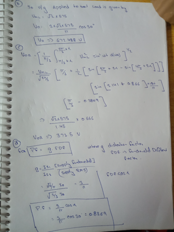
 2. Figure 2 shows a 6-pulse thyristor rectifier feeding a DC static load an operating at steady-state. The ac input power supply is a symmetric set of three-phase voltages forming a direct sequence, having rms line-to-line voltage of Vuns equal to 415 V and angular frequency ω equal to 100π rad/s. The load is sufficiently inductive to smooth out the load current i(t), i.e. i 1, where I is a constant. a. Derive the mathematical expression of the average DC...
 can you calculate and explain why? thanks
A single-phase thyristor rectifier as 50 Hz source. The rectifier delivers a DC voltage of 150 V to a highly inductive depicted in Figure 1 is fed from a 220 V rms, 1. load with a resistive value of 10 Q. SCR, T SCR2 + is Vo SCR3 SCR T Figure 1 (a) for a delay angle component indicating its phase shift with respect to the input voltage v, Sketch the net rectifier...
can you calculate and explain why? thanks
A single-phase thyristor rectifier as 50 Hz source. The rectifier delivers a DC voltage of 150 V to a highly inductive depicted in Figure 1 is fed from a 220 V rms, 1. load with a resistive value of 10 Q. SCR, T SCR2 + is Vo SCR3 SCR T Figure 1 (a) for a delay angle component indicating its phase shift with respect to the input voltage v, Sketch the net rectifier...
 A purely inductive, balanced, Y-connected load having an
inductance L per phase, is fed by the three-phase half-bridge
inverter shown below in Figure Q5. The inverter is operated in the
square-wave mode (meaning that the pole voltages are square waves)
with a frequency fs.
A purely inductive, balanced, Y-connected load having an inductance L per phase, is fed biy the three-phase half-bridge inverter shown below in Figure Q5. The inverter is operated in the square-wave mode (meaning that the pole...
A purely inductive, balanced, Y-connected load having an
inductance L per phase, is fed by the three-phase half-bridge
inverter shown below in Figure Q5. The inverter is operated in the
square-wave mode (meaning that the pole voltages are square waves)
with a frequency fs.
A purely inductive, balanced, Y-connected load having an inductance L per phase, is fed biy the three-phase half-bridge inverter shown below in Figure Q5. The inverter is operated in the square-wave mode (meaning that the pole...
 FIND E), F),G)
A three-phase bridge rectifier is shown here. The secondary's phase voltages are: Van (t) = Vm sin (wt), Vbn (t) = Vm sin (ot - 120°), and Ven (t) = Vm sin (ot - 240°), and the corresponding line-to-line voltages are: Vab = V3Vm sin(ot+30°), Vhc = V3Vm sin(ot - 90°), and Vca = V3Vm sin(ot - 210'), where Vm is the peak voltage. Plot the three phase voltages and the three line-to-line voltages. MATLAB is a...
FIND E), F),G)
A three-phase bridge rectifier is shown here. The secondary's phase voltages are: Van (t) = Vm sin (wt), Vbn (t) = Vm sin (ot - 120°), and Ven (t) = Vm sin (ot - 240°), and the corresponding line-to-line voltages are: Vab = V3Vm sin(ot+30°), Vhc = V3Vm sin(ot - 90°), and Vca = V3Vm sin(ot - 210'), where Vm is the peak voltage. Plot the three phase voltages and the three line-to-line voltages. MATLAB is a...
 1. (10 PT) A three-phase bridge rectifier circuit shown in the figure phase voltage of 220 volts rms. A load of 100 Ω is connected across is supplied by a rectifier. Both the primary and secondary windings of transfor Assume the transformer has a turns ratio of unity mer are Y-connected a) 3 PTI On the top of voltage plot on next page indicate the diodes that will be conducting during different intervals of time. b) 17 PT] Plot the...
 4.) Worth 30 Points A controlled single-phase full-wave bridge rectifier has a R load (R = 20 92) and a 120 Vrms, 60 Hz AC Source. The delay angle is 45 degrees. Hint: Use the following equation for this problem. 1. " a sina MR V2 21 44 A. Determine the average current in the load. B. Determine the RMS current in the load. C. Determine the RMS source current. D. Determine the power factor. E. Validate your answers using...
 Can you solve the 3 questions using the posted figure? The wave
form figure is Fig P3-3. The equations for 3-4 are attached too.
Thank you
For the waveforms in Fig. P3-3, calculate their average value and the rms values of the fundamental and the harmonic frequency components. 3-3 34 In the waveforms of Fig. P3-3 of Problem 3-3, A = 10 and u = 20° (14 = u2-u/2), where applicable. Calculate their total rms values as follows: (a) By...
Can you solve the 3 questions using the posted figure? The wave
form figure is Fig P3-3. The equations for 3-4 are attached too.
Thank you
For the waveforms in Fig. P3-3, calculate their average value and the rms values of the fundamental and the harmonic frequency components. 3-3 34 In the waveforms of Fig. P3-3 of Problem 3-3, A = 10 and u = 20° (14 = u2-u/2), where applicable. Calculate their total rms values as follows: (a) By...
 QUESTION 1 (30 points) A high voltage distribution line of 25kV (RMS line to line) is supplied by a generator. The system is shown in Fig. 1.1. synchronous Synchronous motor Distribution Line (3) Synchronous generator Load 2 Load 1 Figure 1.1 The line frequency is 60HZ. Two loads are connected to the line. Load 1 is a bank of 50n resistors connected in star (Y). Load 2 is a bank of 12uF capacitors connected in delta (A). A synchronous motor...
Most questions answered within 3 hours.
-
Where is the error in this code sequence?
String s1 = "Hello";
String s2 = "ello";...
asked 10 months ago -
Financial data for Joel de Paris, Inc., for last year
follow:
Joel de Paris, Inc.
Balance...
asked 10 months ago -
Consider this reaction:
Al2(SO4)3 (aq)+ BaCl3
(aq) Al2Cl6 (aq)- +
3BaSO4(s) . What is the...
asked 10 months ago -
Suppose that Savneet is considering increasing her
recent random sample from 20 car rentals to 40...
asked 10 months ago -
Trucks arrive at an unloading terminal at an average rate of 120
per hour.
Trucks arrive...
asked 10 months ago -
Why are methanol and ethanol completely soluble in water while
octanol is not very little soluble....
asked 10 months ago -
A facilities manager at a university reads in a research report
that the mean amount of...
asked 10 months ago -
When the CuSO4 is rehydrated by adding water to the anhydrous
compound, is this an endothermic...
asked 10 months ago -
A ray of sunlight is passing from diamond into crown glass; the
angle of incidence is...
asked 10 months ago -
A block of mass 0.249 kg is placed on top of a light, vertical
spring of...
asked 10 months ago -
how do the kidneys compensate in the presences of acidosis
a) trigger hyperventilate
b) reserve acid...
asked 10 months ago -
Question 501 pts
The rental rate of capital to the firm increases. Which of the
following...
asked 10 months ago