
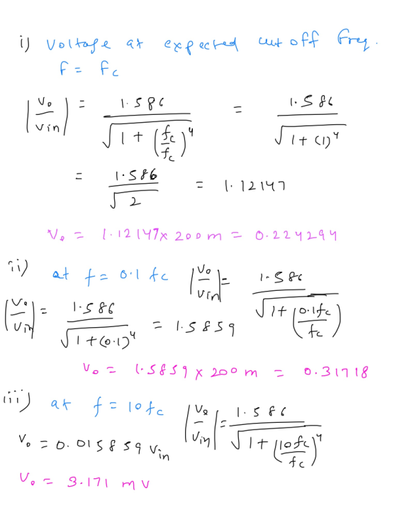
The circuit frequency is equal to the calculated frequency with the circuit input voltage set to 200 mvpp
Acl = 1.586
Homework Answers
Add Answer to:
The circuit frequency is equal to the calculated
frequency with the circuit input voltage set to...
Simulation For each filter mentioned in the following cases, first simulate the circuit using Multisim. You can get a plot of the transfer function that is called the Bode plot. From the right toolba...
 Simulation For each filter mentioned in the following cases, first simulate the circuit using Multisim. You can get a plot of the transfer function that is called the Bode plot. From the right toolbar, select "Bode Plotter". Change initial (I) and final (F) frequencies to 1Hz and 200 KHz, respectively. Use a Voltage AC source as the input signal. You do not need to change any parameter from voltage AC source. Connect "Bode Plotter" to input and output of your...
For each filter mentioned in the following cases, first simulate the circuit using Multisim. You can get a plot of the transfer function that is called the Bode plot. From the right toolbar, select &...
 For each filter mentioned in the following cases, first simulate the circuit using Multisim. You can get a plot of the transfer function that is called the Bode plot. From the right toolbar, select "Bode Plotter". Change initial (I) and final (F frequencies to 1Hz and 200 KHz, respectively. Use a Voltage AC source as the input signal. You do not need to change any parameter from voltage AC source Connect "Bode Plotter" to input and output of your circuit...
C- Amplifier: Consider figure 3. This circuit uses the JFET to amplify the input signal voltage F...
 C- Amplifier: Consider figure 3. This circuit uses the JFET to amplify the input signal voltage First the dc operation must be set. Use equation 1 and your previous data to calculate the value of Vas required to give I-0.5 mA. Determine the source resistance Rs needed to set this bias. Set up the circuit of figure 3 with your calculated value of Rs. Measure Vo and Vs to determine if your operating conditions are correct. Apply an input voltage...
Solve: For the circuit below, using a 2N7000 N-Channel MOSFET, VDD Of 20 V, V 1V...
 Solve: For the circuit below, using a 2N7000 N-Channel MOSFET, VDD Of 20 V, V 1V and (kn'w/L)- 100umohs, calculate Vo, Vo and Vs and lo. Then, set an input signal Vin 25mV peak amplitude with a frequency of 1kHz. Calculate the voltage gain (Von/Vn) + VDD RG1 V 390 kn RD VRD 堲 C. C1 M1 IG=01- 10μ5 2N7000/PLP 2N7000/PLPRLoad VGS V, GS RS 15F 0.47k CS RS CS DC measurements: Calculated AC measurements: A VV Calculated
1. Set up the following circuit. (20pts) 5 Vp-p R2 Vo Use the function generator to set up signal (5 Vpp sinusoidal...
 1. Set up the following circuit. (20pts) 5 Vp-p R2 Vo Use the function generator to set up signal (5 Vpp sinusoidal with a 5 V DC offset) as the input voltage (Vin) and take the output voltage (Vo) across R Sketch and label the input voltage (Vin) and actual output voltage (Vo) displayed on the Oscilloscope and compare actual Vo to your calculated output Vo. (Show your all work for your calculation to get a full credit.) You should...
The input voltage vin t for the circuit shown is the sine curve in the graph...
 The input voltage vin t for the circuit shown is the sine curve in the graph below f R-2 k, what value must be chosen for the capacitor so that the peak to peak output amplitude is 2 V ? in(t) (V) 3 t (ms) 10 Express your answer to three signficant figures in μF View Available Hint(s) C= AF
1. As a reference, observe the full amplitude range of the AC voltage, without limiting. R1...
 1. As a reference, observe the full amplitude range of the AC voltage, without limiting. R1 330 0 f=1.0 kHz 3.0 k2 out Vap = 15.0 V Figure 1. AC Circuit without limiter Construct the circuit of Figure 1. Set the function generator for a sine wave with a frequency of about 1 kHz. Begin with the AC input voltage adjusted to its minimum value, approximately 0 V. Connect Channel 1 of the oscilloscope to observe the AC input voltag...
At what frequency will the output voltage vo(t)in Fig. 9.39 be equal to the input voltage...
 At what frequency will the output voltage vo(t)in Fig. 9.39 be equal to the input voltage v(t)? 12 Holt) Figure 9.39 For Review Question 9.8. (a) 0 rad/s (b) 1 rad/s (c) 4 rad/s (d) oo rad/s (e) none of the above
Re-submission of question. Consider the Full-bridge single-phase inverter with input voltage equal to 100V. This inverter...
Re-submission of question. Consider the Full-bridge single-phase inverter with input voltage equal to 100V. This inverter is controlled by single PWM technique with amplitude modulalation index equal to 0.5 to generate a 3-level half-wave symmetry waveform with frequency equal to 50 Hz. (a) Draw its power circuit. [solved by an expert] (b) Obtain the switching table. [ solved by an expert] (c) Calculate the width of each generated pulses at the output voltage.[solved by an expert] (d) Calculate the RMS...
 Simulation For each filter mentioned in the following cases, first simulate the circuit using Multisim. You can get a plot of the transfer function that is called the Bode plot. From the right toolbar, select "Bode Plotter". Change initial (I) and final (F) frequencies to 1Hz and 200 KHz, respectively. Use a Voltage AC source as the input signal. You do not need to change any parameter from voltage AC source. Connect "Bode Plotter" to input and output of your...
 For each filter mentioned in the following cases, first simulate the circuit using Multisim. You can get a plot of the transfer function that is called the Bode plot. From the right toolbar, select "Bode Plotter". Change initial (I) and final (F frequencies to 1Hz and 200 KHz, respectively. Use a Voltage AC source as the input signal. You do not need to change any parameter from voltage AC source Connect "Bode Plotter" to input and output of your circuit...
 C- Amplifier: Consider figure 3. This circuit uses the JFET to amplify the input signal voltage First the dc operation must be set. Use equation 1 and your previous data to calculate the value of Vas required to give I-0.5 mA. Determine the source resistance Rs needed to set this bias. Set up the circuit of figure 3 with your calculated value of Rs. Measure Vo and Vs to determine if your operating conditions are correct. Apply an input voltage...
 Solve: For the circuit below, using a 2N7000 N-Channel MOSFET, VDD Of 20 V, V 1V and (kn'w/L)- 100umohs, calculate Vo, Vo and Vs and lo. Then, set an input signal Vin 25mV peak amplitude with a frequency of 1kHz. Calculate the voltage gain (Von/Vn) + VDD RG1 V 390 kn RD VRD 堲 C. C1 M1 IG=01- 10μ5 2N7000/PLP 2N7000/PLPRLoad VGS V, GS RS 15F 0.47k CS RS CS DC measurements: Calculated AC measurements: A VV Calculated
 1. Set up the following circuit. (20pts) 5 Vp-p R2 Vo Use the function generator to set up signal (5 Vpp sinusoidal with a 5 V DC offset) as the input voltage (Vin) and take the output voltage (Vo) across R Sketch and label the input voltage (Vin) and actual output voltage (Vo) displayed on the Oscilloscope and compare actual Vo to your calculated output Vo. (Show your all work for your calculation to get a full credit.) You should...
 The input voltage vin t for the circuit shown is the sine curve in the graph below f R-2 k, what value must be chosen for the capacitor so that the peak to peak output amplitude is 2 V ? in(t) (V) 3 t (ms) 10 Express your answer to three signficant figures in μF View Available Hint(s) C= AF
 1. As a reference, observe the full amplitude range of the AC voltage, without limiting. R1 330 0 f=1.0 kHz 3.0 k2 out Vap = 15.0 V Figure 1. AC Circuit without limiter Construct the circuit of Figure 1. Set the function generator for a sine wave with a frequency of about 1 kHz. Begin with the AC input voltage adjusted to its minimum value, approximately 0 V. Connect Channel 1 of the oscilloscope to observe the AC input voltag...
 At what frequency will the output voltage vo(t)in Fig. 9.39 be equal to the input voltage v(t)? 12 Holt) Figure 9.39 For Review Question 9.8. (a) 0 rad/s (b) 1 rad/s (c) 4 rad/s (d) oo rad/s (e) none of the above
Most questions answered within 3 hours.
-
Where is the error in this code sequence?
String s1 = "Hello";
String s2 = "ello";...
asked 10 months ago -
Financial data for Joel de Paris, Inc., for last year
follow:
Joel de Paris, Inc.
Balance...
asked 10 months ago -
Consider this reaction:
Al2(SO4)3 (aq)+ BaCl3
(aq) Al2Cl6 (aq)- +
3BaSO4(s) . What is the...
asked 10 months ago -
Suppose that Savneet is considering increasing her
recent random sample from 20 car rentals to 40...
asked 10 months ago -
Trucks arrive at an unloading terminal at an average rate of 120
per hour.
Trucks arrive...
asked 10 months ago -
Why are methanol and ethanol completely soluble in water while
octanol is not very little soluble....
asked 10 months ago -
A facilities manager at a university reads in a research report
that the mean amount of...
asked 10 months ago -
When the CuSO4 is rehydrated by adding water to the anhydrous
compound, is this an endothermic...
asked 10 months ago -
A ray of sunlight is passing from diamond into crown glass; the
angle of incidence is...
asked 10 months ago -
A block of mass 0.249 kg is placed on top of a light, vertical
spring of...
asked 10 months ago -
how do the kidneys compensate in the presences of acidosis
a) trigger hyperventilate
b) reserve acid...
asked 10 months ago -
Question 501 pts
The rental rate of capital to the firm increases. Which of the
following...
asked 10 months ago