
Homework Answers

Add Answer to:
Problems for Figures P11-77 to P11-84 Each Figure shows a mechanical device in which one or...
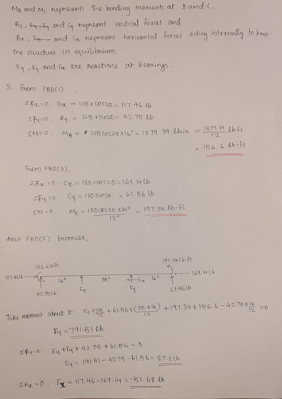
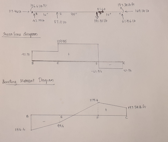
The figure shows a mechanical device in which force (s) are applied parallel to and away...
 The figure shows a mechanical device in which force
(s) are applied parallel to and away from the axis of the main,
beam-like part. The device is supported by bearings at the
locations marked with an X, which can provide reaction forces in
any direction perpendicular to the axis of the beam. One of the
bearings has the capability of resisting horizontally directed
forces
1. Break the compound beam into parts consisting of each of the
straight components.
2. Show...
The figure shows a mechanical device in which force
(s) are applied parallel to and away from the axis of the main,
beam-like part. The device is supported by bearings at the
locations marked with an X, which can provide reaction forces in
any direction perpendicular to the axis of the beam. One of the
bearings has the capability of resisting horizontally directed
forces
1. Break the compound beam into parts consisting of each of the
straight components.
2. Show...
The single-story unbraced frame shown below is subjected to dead load, roof live load, and wind load Figure 1 shows the...
 The single-story unbraced frame shown below is subjected to dead load, roof live load, and wind load Figure 1 shows the results of a first-order analysis relative to the columns of the frame. The axial load and end moment (also equal to the maximum moment in the column) are given separately for the different load cases (i.e., dead load, roof live load, and lateral wind load). All vertical loads are symmetrically placed and contribute only to the Mnt moments (i.e.,...
Auge Steel Framing Details 1. Complete all light g auge steel componente ir the following wall se...
 auge Steel Framing Details 1. Complete all light g auge steel componente ir the following wall section, including floor joists, wall studs, roof rafters, and required clips angles, stiffeners, and fasteners. Label all components. Roof sheathing Wall sheathing 。 Interior wallboard Subflooring Foundation 103 Scale: l square =2" (50 mm) Name: necessity of cutting holes in m on the construction ste 12.11. 12.15). Thack etions a sed for top and bottom plates, e construction, shemperature that col tural shapes. Prers...
 The figure shows a mechanical device in which force
(s) are applied parallel to and away from the axis of the main,
beam-like part. The device is supported by bearings at the
locations marked with an X, which can provide reaction forces in
any direction perpendicular to the axis of the beam. One of the
bearings has the capability of resisting horizontally directed
forces
1. Break the compound beam into parts consisting of each of the
straight components.
2. Show...
The figure shows a mechanical device in which force
(s) are applied parallel to and away from the axis of the main,
beam-like part. The device is supported by bearings at the
locations marked with an X, which can provide reaction forces in
any direction perpendicular to the axis of the beam. One of the
bearings has the capability of resisting horizontally directed
forces
1. Break the compound beam into parts consisting of each of the
straight components.
2. Show...
 The single-story unbraced frame shown below is subjected to dead load, roof live load, and wind load Figure 1 shows the results of a first-order analysis relative to the columns of the frame. The axial load and end moment (also equal to the maximum moment in the column) are given separately for the different load cases (i.e., dead load, roof live load, and lateral wind load). All vertical loads are symmetrically placed and contribute only to the Mnt moments (i.e.,...
 auge Steel Framing Details 1. Complete all light g auge steel componente ir the following wall section, including floor joists, wall studs, roof rafters, and required clips angles, stiffeners, and fasteners. Label all components. Roof sheathing Wall sheathing 。 Interior wallboard Subflooring Foundation 103 Scale: l square =2" (50 mm) Name: necessity of cutting holes in m on the construction ste 12.11. 12.15). Thack etions a sed for top and bottom plates, e construction, shemperature that col tural shapes. Prers...
Most questions answered within 3 hours.
-
Where is the error in this code sequence?
String s1 = "Hello";
String s2 = "ello";...
asked 10 months ago -
Financial data for Joel de Paris, Inc., for last year
follow:
Joel de Paris, Inc.
Balance...
asked 10 months ago -
Consider this reaction:
Al2(SO4)3 (aq)+ BaCl3
(aq) Al2Cl6 (aq)- +
3BaSO4(s) . What is the...
asked 10 months ago -
Suppose that Savneet is considering increasing her
recent random sample from 20 car rentals to 40...
asked 10 months ago -
Trucks arrive at an unloading terminal at an average rate of 120
per hour.
Trucks arrive...
asked 10 months ago -
Why are methanol and ethanol completely soluble in water while
octanol is not very little soluble....
asked 10 months ago -
A facilities manager at a university reads in a research report
that the mean amount of...
asked 10 months ago -
When the CuSO4 is rehydrated by adding water to the anhydrous
compound, is this an endothermic...
asked 10 months ago -
A ray of sunlight is passing from diamond into crown glass; the
angle of incidence is...
asked 10 months ago -
A block of mass 0.249 kg is placed on top of a light, vertical
spring of...
asked 10 months ago -
how do the kidneys compensate in the presences of acidosis
a) trigger hyperventilate
b) reserve acid...
asked 10 months ago -
Question 501 pts
The rental rate of capital to the firm increases. Which of the
following...
asked 10 months ago