


Homework Answers
Add Answer to:
Will rate!!
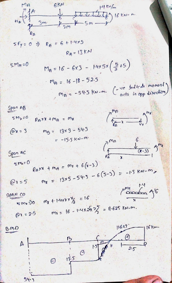
6 kN 1.4kN m 16 KN m 1:3 Now draw the moment diagram for...
Draw the moment diagram for the beam. Begin by placing the lines of discontinuity. Place the...
 Draw the moment diagram for the beam. Begin by placing the lines of discontinuity. Place the appropriate function between the lines of discontinuity, ensuring the endpoints have the correct values Note-Make sure you place only one vertical line at places that require a vertical line. If you inadvertently place two vertical lines at the same place, it will appear visually correct because the lines overlap, but the system will mark it wrong. add vertical line off delete +add segment ?reset...
Using the differential and integral relations between the load and the shear, draw the shear diagram...
 Using the differential and integral relations between the load and the shear, draw the shear diagram for this beam. Begin by placing the lines of discontinuity. Place the appropriate function between the lines of discontinuity, ensuring the endpoints have the correct values. Note - Make sure you place only one vertical line at places that require a vertical line. If you inadvertently place 2 vertical lines at the same place, it will appear correct visually because the lines overlap, but...
Problem 7.56 4 of 4 Part A Draw the shear diagram for the beam. Follow the...
 Problem 7.56 4 of 4 Part A Draw the shear diagram for the beam. Follow the sign convention. (Figure 1) Click on "add vertical line off" to add discontinuity lines. Then click on "add segment" button to add functions between the lines. Note 1- Make sure you place only one vertical line at places that require a vertical line. If you inadvertently place two vertical lines at the same place, it will appear correct visually because the lines overlap, but...
The lines Click on "add verticall line Note off to add discontinuity lines. Then click on "add se...
 the lines Click on "add verticall line Note off to add discontinuity lines. Then click on "add segment" button to add functions line at appear visually correct because the lines overlap, but the system will mark it by a roller at C.(Figure ) 600 N 400 N m 1o1 600 N 400 N im m) 2 m 2 m 1 23 of 51 Draw the moment diagram for the beam. Click on "add vertical line off" to add discontinuity lines....
Please answer this question in one hour. Problem 6.13 Part A Draw the shear diagram for...
 Please answer this question in one hour.
Problem 6.13 Part A Draw the shear diagram for the beam. Assume that Mo 200 lb.ft, and L 20 ft. Begin by placing the lines of discontinuity. Place the appropriate function between the lines of discontinuity, ensuring the endpoints have the correct values Note Make sure you place only one vertical line at places that require a vertical line. If you inadvertently place two vertical lines at the same place, it will appear...
Please answer this question in one hour.
Problem 6.13 Part A Draw the shear diagram for the beam. Assume that Mo 200 lb.ft, and L 20 ft. Begin by placing the lines of discontinuity. Place the appropriate function between the lines of discontinuity, ensuring the endpoints have the correct values Note Make sure you place only one vertical line at places that require a vertical line. If you inadvertently place two vertical lines at the same place, it will appear...
1 Review - Part B Draw the moment diagrams for the beam shown in (Figure 1)...
 1 Review - Part B Draw the moment diagrams for the beam shown in (Figure 1) using the method of superposition. Consider the beam to be cantilevered from the support at (BV). Follow the sign convention. Draw the moment diagram for the force shown in the figure below. Click on "add vertical line off" to add vertical lines. Then click on "add segment" button to add functions between the lines. Note 1 - Make sure you place only one vertical...
draw the shear and moment diagram, Part A Draw the shear diagram for the beam Follow...
 draw the shear and moment diagram,
Part A Draw the shear diagram for the beam Follow the sign convention Click on "add vertical line off to add discontinuity lines. Then click on "add segment" button to add functions between the lines. Note 1 Make sure you place only one vertical line at places that require a vertical line. If you inadvertently place two vertical lines at the same place, it will appear con it wrong Note 2 The curve you...
draw the shear and moment diagram,
Part A Draw the shear diagram for the beam Follow the sign convention Click on "add vertical line off to add discontinuity lines. Then click on "add segment" button to add functions between the lines. Note 1 Make sure you place only one vertical line at places that require a vertical line. If you inadvertently place two vertical lines at the same place, it will appear con it wrong Note 2 The curve you...
Please graph it on the uploaded chart Consider a cantilever beam shown in the figure below....
 Please graph it on the uploaded chart
Consider a cantilever beam shown in the figure below. Figure 1) Part A Draw the shear diagram for the beam Click on "add vertical line off" to add discontinuity lines. Then click on "add segment" button to add functions between the lines Note - Make sure you place only one vertical line at places that require a vertical line. If you inadvertently place two vertical lines at the same place, it will appear...
Please graph it on the uploaded chart
Consider a cantilever beam shown in the figure below. Figure 1) Part A Draw the shear diagram for the beam Click on "add vertical line off" to add discontinuity lines. Then click on "add segment" button to add functions between the lines Note - Make sure you place only one vertical line at places that require a vertical line. If you inadvertently place two vertical lines at the same place, it will appear...
Can someone solve A&B for me please. I need an accurate draw. Part A Draw the shear diagram for the beam. Follo...
 Can
someone solve A&B for me please. I need an accurate draw.
Part A Draw the shear diagram for the beam. Follow the sign convention. (Figure 1) Click on "add vertical line off" to add discontinulty lines. Then clic functions between the lines. Note Make sure you place only one vertical line at places that require a vertical line. If you i place 2 vertical lines at the same place, it will appear correct visually because the lines overl system...
Can
someone solve A&B for me please. I need an accurate draw.
Part A Draw the shear diagram for the beam. Follow the sign convention. (Figure 1) Click on "add vertical line off" to add discontinulty lines. Then clic functions between the lines. Note Make sure you place only one vertical line at places that require a vertical line. If you i place 2 vertical lines at the same place, it will appear correct visually because the lines overl system...
Homework 8: Bending (Chapter 6) roblem 6.35 Review A beam is shown in the figure below. (Figure 1...
 need answers for the shear and moment as well as part F
Homework 8: Bending (Chapter 6) roblem 6.35 Review A beam is shown in the figure below. (Figure 1) Figure 1 of 1> 400 N/m 200 N/m 3 3 m 20 of 51 Draw the shear diagram for the beam Note 1 - The curve you choose from the drop-down is only a pictorial representation of a real quadraticlcubic curve. The You should not Note - Make sure you...
need answers for the shear and moment as well as part F
Homework 8: Bending (Chapter 6) roblem 6.35 Review A beam is shown in the figure below. (Figure 1) Figure 1 of 1> 400 N/m 200 N/m 3 3 m 20 of 51 Draw the shear diagram for the beam Note 1 - The curve you choose from the drop-down is only a pictorial representation of a real quadraticlcubic curve. The You should not Note - Make sure you...
 Draw the moment diagram for the beam. Begin by placing the lines of discontinuity. Place the appropriate function between the lines of discontinuity, ensuring the endpoints have the correct values Note-Make sure you place only one vertical line at places that require a vertical line. If you inadvertently place two vertical lines at the same place, it will appear visually correct because the lines overlap, but the system will mark it wrong. add vertical line off delete +add segment ?reset...
 Using the differential and integral relations between the load and the shear, draw the shear diagram for this beam. Begin by placing the lines of discontinuity. Place the appropriate function between the lines of discontinuity, ensuring the endpoints have the correct values. Note - Make sure you place only one vertical line at places that require a vertical line. If you inadvertently place 2 vertical lines at the same place, it will appear correct visually because the lines overlap, but...
 Problem 7.56 4 of 4 Part A Draw the shear diagram for the beam. Follow the sign convention. (Figure 1) Click on "add vertical line off" to add discontinuity lines. Then click on "add segment" button to add functions between the lines. Note 1- Make sure you place only one vertical line at places that require a vertical line. If you inadvertently place two vertical lines at the same place, it will appear correct visually because the lines overlap, but...
 the lines Click on "add verticall line Note off to add discontinuity lines. Then click on "add segment" button to add functions line at appear visually correct because the lines overlap, but the system will mark it by a roller at C.(Figure ) 600 N 400 N m 1o1 600 N 400 N im m) 2 m 2 m 1 23 of 51 Draw the moment diagram for the beam. Click on "add vertical line off" to add discontinuity lines....
 Please answer this question in one hour.
Problem 6.13 Part A Draw the shear diagram for the beam. Assume that Mo 200 lb.ft, and L 20 ft. Begin by placing the lines of discontinuity. Place the appropriate function between the lines of discontinuity, ensuring the endpoints have the correct values Note Make sure you place only one vertical line at places that require a vertical line. If you inadvertently place two vertical lines at the same place, it will appear...
Please answer this question in one hour.
Problem 6.13 Part A Draw the shear diagram for the beam. Assume that Mo 200 lb.ft, and L 20 ft. Begin by placing the lines of discontinuity. Place the appropriate function between the lines of discontinuity, ensuring the endpoints have the correct values Note Make sure you place only one vertical line at places that require a vertical line. If you inadvertently place two vertical lines at the same place, it will appear...
 1 Review - Part B Draw the moment diagrams for the beam shown in (Figure 1) using the method of superposition. Consider the beam to be cantilevered from the support at (BV). Follow the sign convention. Draw the moment diagram for the force shown in the figure below. Click on "add vertical line off" to add vertical lines. Then click on "add segment" button to add functions between the lines. Note 1 - Make sure you place only one vertical...
 draw the shear and moment diagram,
Part A Draw the shear diagram for the beam Follow the sign convention Click on "add vertical line off to add discontinuity lines. Then click on "add segment" button to add functions between the lines. Note 1 Make sure you place only one vertical line at places that require a vertical line. If you inadvertently place two vertical lines at the same place, it will appear con it wrong Note 2 The curve you...
draw the shear and moment diagram,
Part A Draw the shear diagram for the beam Follow the sign convention Click on "add vertical line off to add discontinuity lines. Then click on "add segment" button to add functions between the lines. Note 1 Make sure you place only one vertical line at places that require a vertical line. If you inadvertently place two vertical lines at the same place, it will appear con it wrong Note 2 The curve you...
 Please graph it on the uploaded chart
Consider a cantilever beam shown in the figure below. Figure 1) Part A Draw the shear diagram for the beam Click on "add vertical line off" to add discontinuity lines. Then click on "add segment" button to add functions between the lines Note - Make sure you place only one vertical line at places that require a vertical line. If you inadvertently place two vertical lines at the same place, it will appear...
Please graph it on the uploaded chart
Consider a cantilever beam shown in the figure below. Figure 1) Part A Draw the shear diagram for the beam Click on "add vertical line off" to add discontinuity lines. Then click on "add segment" button to add functions between the lines Note - Make sure you place only one vertical line at places that require a vertical line. If you inadvertently place two vertical lines at the same place, it will appear...
 Can
someone solve A&B for me please. I need an accurate draw.
Part A Draw the shear diagram for the beam. Follow the sign convention. (Figure 1) Click on "add vertical line off" to add discontinulty lines. Then clic functions between the lines. Note Make sure you place only one vertical line at places that require a vertical line. If you i place 2 vertical lines at the same place, it will appear correct visually because the lines overl system...
Can
someone solve A&B for me please. I need an accurate draw.
Part A Draw the shear diagram for the beam. Follow the sign convention. (Figure 1) Click on "add vertical line off" to add discontinulty lines. Then clic functions between the lines. Note Make sure you place only one vertical line at places that require a vertical line. If you i place 2 vertical lines at the same place, it will appear correct visually because the lines overl system...
 need answers for the shear and moment as well as part F
Homework 8: Bending (Chapter 6) roblem 6.35 Review A beam is shown in the figure below. (Figure 1) Figure 1 of 1> 400 N/m 200 N/m 3 3 m 20 of 51 Draw the shear diagram for the beam Note 1 - The curve you choose from the drop-down is only a pictorial representation of a real quadraticlcubic curve. The You should not Note - Make sure you...
need answers for the shear and moment as well as part F
Homework 8: Bending (Chapter 6) roblem 6.35 Review A beam is shown in the figure below. (Figure 1) Figure 1 of 1> 400 N/m 200 N/m 3 3 m 20 of 51 Draw the shear diagram for the beam Note 1 - The curve you choose from the drop-down is only a pictorial representation of a real quadraticlcubic curve. The You should not Note - Make sure you...
Most questions answered within 3 hours.
-
Where is the error in this code sequence?
String s1 = "Hello";
String s2 = "ello";...
asked 11 months ago -
Financial data for Joel de Paris, Inc., for last year
follow:
Joel de Paris, Inc.
Balance...
asked 11 months ago -
Consider this reaction:
Al2(SO4)3 (aq)+ BaCl3
(aq) Al2Cl6 (aq)- +
3BaSO4(s) . What is the...
asked 11 months ago -
Suppose that Savneet is considering increasing her
recent random sample from 20 car rentals to 40...
asked 11 months ago -
Trucks arrive at an unloading terminal at an average rate of 120
per hour.
Trucks arrive...
asked 11 months ago -
Why are methanol and ethanol completely soluble in water while
octanol is not very little soluble....
asked 11 months ago -
A facilities manager at a university reads in a research report
that the mean amount of...
asked 11 months ago -
When the CuSO4 is rehydrated by adding water to the anhydrous
compound, is this an endothermic...
asked 11 months ago -
A ray of sunlight is passing from diamond into crown glass; the
angle of incidence is...
asked 11 months ago -
A block of mass 0.249 kg is placed on top of a light, vertical
spring of...
asked 11 months ago -
how do the kidneys compensate in the presences of acidosis
a) trigger hyperventilate
b) reserve acid...
asked 11 months ago -
Question 501 pts
The rental rate of capital to the firm increases. Which of the
following...
asked 11 months ago