
Homework Answers


 plzzzz rate
it.................
plzzzz rate
it.................
Add Answer to:
Two carts with rolling friction coefficient fa are connected as shown below. Input is force u(t),...
Problem (2): Problem (3): Two carts with negligible rolling friction are connected as shown in the...
 Problem (2): Problem (3): Two carts with negligible rolling friction are connected as shown in the Figure. The input force is u (t) and the output is the position o cart 2, that is q(t). Determine the transfer function Q(s) / U(s) when m, = 3; m2 =2; k, = kz = 3; b. = b = 0.5 Input force Two carts with age rolling friction of oil each
Given a zero-state LTI system whose impulse response h(t) = u(t) u(t-2), if the input of...
 Given a zero-state LTI system whose impulse response h(t) = u(t) u(t-2), if the input of the system is r(t), find the system equation which relates the input to the output y(t) 4. (20 points) If a causal signal's s-domain representation is given as X (s) = (s+ 2)(s2 +2s + 5) (a) find all the poles and zero of the function. 2 1 52243 orr
7. Consider the mechanical system shown below. The system initially at rest. The displacements u, y,...
 7. Consider the mechanical system shown below. The system initially at rest. The displacements u, y, and z are measured from their respective rest positions. Given that u is the input, y is the output, 1) Obtain the transfer function of the system (20pt). 2) Obtain a state-space representation of the system (20pt). I b, - obteranlara k, 12 WI
10.Represent the translational mechanical system shown in the Figure in state- space, where xX3(t) is the...
 10.Represent the translational mechanical system shown in the Figure in state- space, where xX3(t) is the output IN- 11.Find the state equations and output equation for the phase-variable representation of the transfer function G(s) 2s+1/(s2+7s+ 9) 12. Convert the state and output equations shown to a transfer function. -1.5 2 u(t) X = X 4 0 Y [1.5 0.625]x 13. For each system shown, write the state equations and the output equation for the phase- variable representation 8s10 sh25 t26...
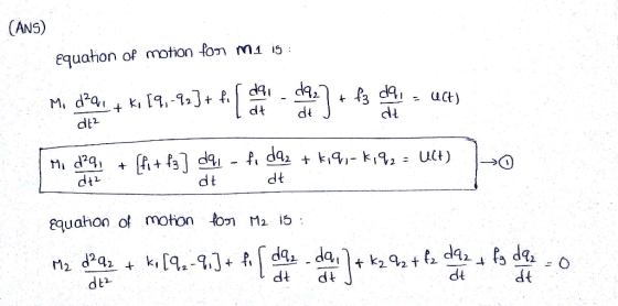
. (40pts) Consider a spring-mass-damper system shown below, where the input u() is displacement input at...
 . (40pts) Consider a spring-mass-damper system shown below, where the input u() is displacement input at the right end of the spring k3 and x() is the displacement of mass ml. (Note that the input is displacement, NOT force) k3 k1 m2 (a) (10pts) Draw necessary free-body diagrams, and the governing equations of motion of the system. (b) (10pts) Find the transfer function from the input u() to the output x(t). (c) (10pts) Given the system parameter values of m1-m2-1,...
Consider the mechanical dynamics of a 2DOF rotary motion system shown below, where the torque is...
 Consider the mechanical dynamics of a 2DOF rotary motion system shown below, where the torque is applied to the right shaft but the angular position of the left shaft is to be controlled, k is the stiffness of the linear rotary spring and b is the viscous friction coefficient of the ball bearing that supports the right shaft and acts as a linear viscous damper with rotary motion. The left shaft is only supported by the right shaft, so there...
(1) In the system shown below, the input is the ideal current source *i,' is and...
 (1) In the system shown below, the input is the ideal current source *i,' is and the output is the voltage across the inductor L1I'. Derive the governing differential equations for the circuit shown below and represent them in state space form. 41-K The state variable R2 L1 R3 Vc C1
Please help me with QUESTION 2. 1. Consider the electrical system shown below, for which the input variable u, the out...
 Please help me with QUESTION 2.
1. Consider the electrical system shown below, for which the input variable u, the output variable y, and the state variables xi and x2 have been specified. R L + C (a) Determine the state-space model of the system (b) Show that the transfer function (from u to y) has the form bis H(s)=2+ajs+ a0 by relating (ao, ai, bi) to (R, L, C) (c) Show that the frequency response function (from u to...
Please help me with QUESTION 2.
1. Consider the electrical system shown below, for which the input variable u, the output variable y, and the state variables xi and x2 have been specified. R L + C (a) Determine the state-space model of the system (b) Show that the transfer function (from u to y) has the form bis H(s)=2+ajs+ a0 by relating (ao, ai, bi) to (R, L, C) (c) Show that the frequency response function (from u to...
Question 4 Suppose we are given a system which is initially at rest with input u(t)...
 Question 4 Suppose we are given a system which is initially at rest with input u(t) and output x(1) described by the differential equation x - 6x + 13x = 2ủ + u 41 Write down the transfer function G(p) for the system and say with adequate justification if this system is stable or not 42 Use the initial value theorem to find g(0+) where g(t) = 1-'[G(p)] (3) 43 Can we, in this case, trust the final value theorem...
Consider the following circuits connected in series. The input is the voltage x(t), the output to...
 Consider the following circuits connected in series. The input is the voltage x(t), the output to system Si is the voltage y(t), and the output of system S2 is the voltage y(t). The differential equation relating the input X(t) to the output yı(t) was found in Homework #3. S2 x(1) y(t) | X(t) 6+ R yce) .66) (1) + y(t) Let L = 0.01, C1 = 0.01, R = 100, C2 = 0.002, and R2 = 50. a) Find the...
 Problem (2): Problem (3): Two carts with negligible rolling friction are connected as shown in the Figure. The input force is u (t) and the output is the position o cart 2, that is q(t). Determine the transfer function Q(s) / U(s) when m, = 3; m2 =2; k, = kz = 3; b. = b = 0.5 Input force Two carts with age rolling friction of oil each
 Given a zero-state LTI system whose impulse response h(t) = u(t) u(t-2), if the input of the system is r(t), find the system equation which relates the input to the output y(t) 4. (20 points) If a causal signal's s-domain representation is given as X (s) = (s+ 2)(s2 +2s + 5) (a) find all the poles and zero of the function. 2 1 52243 orr
 7. Consider the mechanical system shown below. The system initially at rest. The displacements u, y, and z are measured from their respective rest positions. Given that u is the input, y is the output, 1) Obtain the transfer function of the system (20pt). 2) Obtain a state-space representation of the system (20pt). I b, - obteranlara k, 12 WI
 10.Represent the translational mechanical system shown in the Figure in state- space, where xX3(t) is the output IN- 11.Find the state equations and output equation for the phase-variable representation of the transfer function G(s) 2s+1/(s2+7s+ 9) 12. Convert the state and output equations shown to a transfer function. -1.5 2 u(t) X = X 4 0 Y [1.5 0.625]x 13. For each system shown, write the state equations and the output equation for the phase- variable representation 8s10 sh25 t26...
 . (40pts) Consider a spring-mass-damper system shown below, where the input u() is displacement input at the right end of the spring k3 and x() is the displacement of mass ml. (Note that the input is displacement, NOT force) k3 k1 m2 (a) (10pts) Draw necessary free-body diagrams, and the governing equations of motion of the system. (b) (10pts) Find the transfer function from the input u() to the output x(t). (c) (10pts) Given the system parameter values of m1-m2-1,...
 Consider the mechanical dynamics of a 2DOF rotary motion system shown below, where the torque is applied to the right shaft but the angular position of the left shaft is to be controlled, k is the stiffness of the linear rotary spring and b is the viscous friction coefficient of the ball bearing that supports the right shaft and acts as a linear viscous damper with rotary motion. The left shaft is only supported by the right shaft, so there...
 (1) In the system shown below, the input is the ideal current source *i,' is and the output is the voltage across the inductor L1I'. Derive the governing differential equations for the circuit shown below and represent them in state space form. 41-K The state variable R2 L1 R3 Vc C1
 Please help me with QUESTION 2.
1. Consider the electrical system shown below, for which the input variable u, the output variable y, and the state variables xi and x2 have been specified. R L + C (a) Determine the state-space model of the system (b) Show that the transfer function (from u to y) has the form bis H(s)=2+ajs+ a0 by relating (ao, ai, bi) to (R, L, C) (c) Show that the frequency response function (from u to...
Please help me with QUESTION 2.
1. Consider the electrical system shown below, for which the input variable u, the output variable y, and the state variables xi and x2 have been specified. R L + C (a) Determine the state-space model of the system (b) Show that the transfer function (from u to y) has the form bis H(s)=2+ajs+ a0 by relating (ao, ai, bi) to (R, L, C) (c) Show that the frequency response function (from u to...
 Question 4 Suppose we are given a system which is initially at rest with input u(t) and output x(1) described by the differential equation x - 6x + 13x = 2ủ + u 41 Write down the transfer function G(p) for the system and say with adequate justification if this system is stable or not 42 Use the initial value theorem to find g(0+) where g(t) = 1-'[G(p)] (3) 43 Can we, in this case, trust the final value theorem...
 Consider the following circuits connected in series. The input is the voltage x(t), the output to system Si is the voltage y(t), and the output of system S2 is the voltage y(t). The differential equation relating the input X(t) to the output yı(t) was found in Homework #3. S2 x(1) y(t) | X(t) 6+ R yce) .66) (1) + y(t) Let L = 0.01, C1 = 0.01, R = 100, C2 = 0.002, and R2 = 50. a) Find the...
Most questions answered within 3 hours.
-
Where is the error in this code sequence?
String s1 = "Hello";
String s2 = "ello";...
asked 10 months ago -
Financial data for Joel de Paris, Inc., for last year
follow:
Joel de Paris, Inc.
Balance...
asked 10 months ago -
Consider this reaction:
Al2(SO4)3 (aq)+ BaCl3
(aq) Al2Cl6 (aq)- +
3BaSO4(s) . What is the...
asked 10 months ago -
Suppose that Savneet is considering increasing her
recent random sample from 20 car rentals to 40...
asked 10 months ago -
Trucks arrive at an unloading terminal at an average rate of 120
per hour.
Trucks arrive...
asked 10 months ago -
Why are methanol and ethanol completely soluble in water while
octanol is not very little soluble....
asked 10 months ago -
A facilities manager at a university reads in a research report
that the mean amount of...
asked 10 months ago -
When the CuSO4 is rehydrated by adding water to the anhydrous
compound, is this an endothermic...
asked 10 months ago -
A ray of sunlight is passing from diamond into crown glass; the
angle of incidence is...
asked 10 months ago -
A block of mass 0.249 kg is placed on top of a light, vertical
spring of...
asked 10 months ago -
how do the kidneys compensate in the presences of acidosis
a) trigger hyperventilate
b) reserve acid...
asked 10 months ago -
Question 501 pts
The rental rate of capital to the firm increases. Which of the
following...
asked 10 months ago