
In detail and show all steps
Control systems
Homework Answers
Add Answer to:
In detail and show all steps
Control systems
In the feedback system shown, K 0. s2...
course name: control system topic about root locus please show all your steps to make easier...
 course name: control system
topic about root locus
please show all your steps to make easier for understanding.
1. Determine the stability condition of the systems describe in the first column below. Justify your answer with reason. show all your answers steps Justification Stability condition Systems description dy y +2 y x +3 dt dy -6y= x + dt2 dt provide special condition provide special condition 2. Given the closed loop system in the figure below, analysis the systems given...
course name: control system
topic about root locus
please show all your steps to make easier for understanding.
1. Determine the stability condition of the systems describe in the first column below. Justify your answer with reason. show all your answers steps Justification Stability condition Systems description dy y +2 y x +3 dt dy -6y= x + dt2 dt provide special condition provide special condition 2. Given the closed loop system in the figure below, analysis the systems given...
For each of the following feedback systems a. Sketch the Root Locus b. Indicate if there...
 For each of the following feedback systems a. Sketch the Root Locus b. Indicate if there are break-in and/or break-away points, and how many c. Indicate if there are asymptotes and how many d. Use hand calculations to compute the break-in/break-away points e. Use hand calculations to compute the asymptotes SYSTEMI 1 G(s) = (s2 + 5s + 4)(s2 + 5s +6) H(s) = (s + 0.5) SYSTEM II G(s) = (s2 – 3s + 2) (52 +3s + 2)...
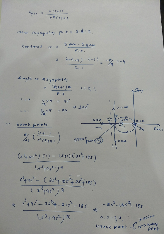
1. The open loop system G()l be placed into a unity feedback system s2(s+1) as shown below. a. Sk...
 please answer all parts and show the related work. thank you!
especially the matlab parts!
1. The open loop system G()l be placed into a unity feedback system s2(s+1) as shown below. a. Sketch the Root Locus of G(s) by hand and compare your results with Matlab. Include your sketch and the Matlab plot. b. This system is unstable for all positive values of K. Explain why. c. Show with a hand sketch and Matlab plot of the root locus...
please answer all parts and show the related work. thank you!
especially the matlab parts!
1. The open loop system G()l be placed into a unity feedback system s2(s+1) as shown below. a. Sketch the Root Locus of G(s) by hand and compare your results with Matlab. Include your sketch and the Matlab plot. b. This system is unstable for all positive values of K. Explain why. c. Show with a hand sketch and Matlab plot of the root locus...
Problem S Consider the control system shown in Figure 4 let Cand G,() -K and Gc...
 Problem S Consider the control system shown in Figure 4 let Cand G,() -K and Gc (s) K (s-1) (s+2) (s+3) (a) Determine the open-loop system (i.e., G (s)) poles and zeros. (b) Determine the number of asymptotes and the angles of asymptotes. (c) Determine the break-in/break-out points (if any) (d) Sketch the root locus (e) Determine the value of K (if any) for which the system is marginally stable
[7] Sketch the root locus for the unity feedback system whose open loop transfer function is K G(s) Draw the root lo...
 [7] Sketch the root locus for the unity feedback system whose open loop transfer function is K G(s) Draw the root locus of the system with the gain Kas a variable. s(s+4) (s2+4s+20) Determine asymptotes, centroid, breakaway point, angle of departure, and the gain at which root locus crosses ja-axis. A control system with type-0 process and a PID controller is shown below. Design the [8 parameters of the PID controller so that the following specifications are satisfied. =100 a)...
9. Consider a negative unity-feedback control system with the loop transfer function s +8 D(s) G(8)=K-...
 9. Consider a negative unity-feedback control system with the loop transfer function s +8 D(s) G(8)=K- s+1) ((s + 1)2 + 22 (s + 94 + 793 + 1932 +33s + 20 (a) Determine the asymptotes of the root-locus diagram for K > 0, if any. (06pts) Answer: The real-axis crossing of the asymptote(s), a = The angle(s) of the asymptote(s), 0q = _ (b) Determine the break-away and the break-in points of the root-locus diagram for K > 0,...
[7] Sketch the root locus for the unity feedback system whose open loop transfer function is K G(s) Draw the root locus...
 [7] Sketch the root locus for the unity feedback system whose open loop transfer function is K G(s) Draw the root locus of the system with the gain K as a variable s(s+4) (s2+4s+20)' Determine asymptotes, centroid,, breakaway point, angle of departure, and the gain at which root locus crosses jw -axis.
[7] Sketch the root locus for the unity feedback system whose open loop transfer function is K G(s) Draw the root locus of the system with the gain...
[7] Sketch the root locus for the unity feedback system whose open loop transfer function is K G(s) Draw the root locus of the system with the gain K as a variable s(s+4) (s2+4s+20)' Determine asymptotes, centroid,, breakaway point, angle of departure, and the gain at which root locus crosses jw -axis.
[7] Sketch the root locus for the unity feedback system whose open loop transfer function is K G(s) Draw the root locus of the system with the gain...
Sketch the root locus for the unity feedback system shown in Figure P8.3 for the following...
 Sketch the root locus for the unity feedback system shown in Figure P8.3 for the following transfer functions: (Section: 8.4] K(s + 2)(8 + 6) a. G(s) = 52 + 8 + 25 K( +4) b. G(S) = FIGURE PR3 152 +1) C G(s) - K(s+1) K (n1)(x + 4) For each system record all steps to sketching the root locus: 1) Identify the # of branches of the system 2) Make sure your sketch is symmetric about the real-axis...
Control System Problem. Please do part A, B , and C. Consider the unity-feedback system with...
 Control System Problem. Please do part A, B , and C.
Consider the unity-feedback system with G(s)-K(st3)(s+5)/(s+(s-7)] Sketch the root locus of this system, clearly finding any asymptotes and calculating any break-in or break-away point:s. Determine the range of gain (K) to ensure that the system is stable Draw the Nyquist diagram of this system, only considering the imaginary axis of the original RHP contour (i.e. between points A and B on the original contour). Hint: You will want to...
Control System Problem. Please do part A, B , and C.
Consider the unity-feedback system with G(s)-K(st3)(s+5)/(s+(s-7)] Sketch the root locus of this system, clearly finding any asymptotes and calculating any break-in or break-away point:s. Determine the range of gain (K) to ensure that the system is stable Draw the Nyquist diagram of this system, only considering the imaginary axis of the original RHP contour (i.e. between points A and B on the original contour). Hint: You will want to...
Question 4 (a) A feedback control system with a proportional controller is shown in Figure Q4...
 Question 4 (a) A feedback control system with a proportional controller is shown in Figure Q4 (a). (i) Sketch the root locus of the system, (ii) Design the proportional controller (choose the value of K) such that the damping ratio does not exceed 0.5 and the time constant is less than 1 second. [All necessary steps of root locus construction and controller design must be shown). C(s) R(S) + s(s+4)(s + 10) Figure Q4 (a). A feedback control system [11...
 course name: control system
topic about root locus
please show all your steps to make easier for understanding.
1. Determine the stability condition of the systems describe in the first column below. Justify your answer with reason. show all your answers steps Justification Stability condition Systems description dy y +2 y x +3 dt dy -6y= x + dt2 dt provide special condition provide special condition 2. Given the closed loop system in the figure below, analysis the systems given...
course name: control system
topic about root locus
please show all your steps to make easier for understanding.
1. Determine the stability condition of the systems describe in the first column below. Justify your answer with reason. show all your answers steps Justification Stability condition Systems description dy y +2 y x +3 dt dy -6y= x + dt2 dt provide special condition provide special condition 2. Given the closed loop system in the figure below, analysis the systems given...
 For each of the following feedback systems a. Sketch the Root Locus b. Indicate if there are break-in and/or break-away points, and how many c. Indicate if there are asymptotes and how many d. Use hand calculations to compute the break-in/break-away points e. Use hand calculations to compute the asymptotes SYSTEMI 1 G(s) = (s2 + 5s + 4)(s2 + 5s +6) H(s) = (s + 0.5) SYSTEM II G(s) = (s2 – 3s + 2) (52 +3s + 2)...
 please answer all parts and show the related work. thank you!
especially the matlab parts!
1. The open loop system G()l be placed into a unity feedback system s2(s+1) as shown below. a. Sketch the Root Locus of G(s) by hand and compare your results with Matlab. Include your sketch and the Matlab plot. b. This system is unstable for all positive values of K. Explain why. c. Show with a hand sketch and Matlab plot of the root locus...
please answer all parts and show the related work. thank you!
especially the matlab parts!
1. The open loop system G()l be placed into a unity feedback system s2(s+1) as shown below. a. Sketch the Root Locus of G(s) by hand and compare your results with Matlab. Include your sketch and the Matlab plot. b. This system is unstable for all positive values of K. Explain why. c. Show with a hand sketch and Matlab plot of the root locus...
 Problem S Consider the control system shown in Figure 4 let Cand G,() -K and Gc (s) K (s-1) (s+2) (s+3) (a) Determine the open-loop system (i.e., G (s)) poles and zeros. (b) Determine the number of asymptotes and the angles of asymptotes. (c) Determine the break-in/break-out points (if any) (d) Sketch the root locus (e) Determine the value of K (if any) for which the system is marginally stable
 [7] Sketch the root locus for the unity feedback system whose open loop transfer function is K G(s) Draw the root locus of the system with the gain Kas a variable. s(s+4) (s2+4s+20) Determine asymptotes, centroid, breakaway point, angle of departure, and the gain at which root locus crosses ja-axis. A control system with type-0 process and a PID controller is shown below. Design the [8 parameters of the PID controller so that the following specifications are satisfied. =100 a)...
 9. Consider a negative unity-feedback control system with the loop transfer function s +8 D(s) G(8)=K- s+1) ((s + 1)2 + 22 (s + 94 + 793 + 1932 +33s + 20 (a) Determine the asymptotes of the root-locus diagram for K > 0, if any. (06pts) Answer: The real-axis crossing of the asymptote(s), a = The angle(s) of the asymptote(s), 0q = _ (b) Determine the break-away and the break-in points of the root-locus diagram for K > 0,...
 [7] Sketch the root locus for the unity feedback system whose open loop transfer function is K G(s) Draw the root locus of the system with the gain K as a variable s(s+4) (s2+4s+20)' Determine asymptotes, centroid,, breakaway point, angle of departure, and the gain at which root locus crosses jw -axis.
[7] Sketch the root locus for the unity feedback system whose open loop transfer function is K G(s) Draw the root locus of the system with the gain...
[7] Sketch the root locus for the unity feedback system whose open loop transfer function is K G(s) Draw the root locus of the system with the gain K as a variable s(s+4) (s2+4s+20)' Determine asymptotes, centroid,, breakaway point, angle of departure, and the gain at which root locus crosses jw -axis.
[7] Sketch the root locus for the unity feedback system whose open loop transfer function is K G(s) Draw the root locus of the system with the gain...
 Sketch the root locus for the unity feedback system shown in Figure P8.3 for the following transfer functions: (Section: 8.4] K(s + 2)(8 + 6) a. G(s) = 52 + 8 + 25 K( +4) b. G(S) = FIGURE PR3 152 +1) C G(s) - K(s+1) K (n1)(x + 4) For each system record all steps to sketching the root locus: 1) Identify the # of branches of the system 2) Make sure your sketch is symmetric about the real-axis...
 Control System Problem. Please do part A, B , and C.
Consider the unity-feedback system with G(s)-K(st3)(s+5)/(s+(s-7)] Sketch the root locus of this system, clearly finding any asymptotes and calculating any break-in or break-away point:s. Determine the range of gain (K) to ensure that the system is stable Draw the Nyquist diagram of this system, only considering the imaginary axis of the original RHP contour (i.e. between points A and B on the original contour). Hint: You will want to...
Control System Problem. Please do part A, B , and C.
Consider the unity-feedback system with G(s)-K(st3)(s+5)/(s+(s-7)] Sketch the root locus of this system, clearly finding any asymptotes and calculating any break-in or break-away point:s. Determine the range of gain (K) to ensure that the system is stable Draw the Nyquist diagram of this system, only considering the imaginary axis of the original RHP contour (i.e. between points A and B on the original contour). Hint: You will want to...
 Question 4 (a) A feedback control system with a proportional controller is shown in Figure Q4 (a). (i) Sketch the root locus of the system, (ii) Design the proportional controller (choose the value of K) such that the damping ratio does not exceed 0.5 and the time constant is less than 1 second. [All necessary steps of root locus construction and controller design must be shown). C(s) R(S) + s(s+4)(s + 10) Figure Q4 (a). A feedback control system [11...
Most questions answered within 3 hours.
-
Where is the error in this code sequence?
String s1 = "Hello";
String s2 = "ello";...
asked 10 months ago -
Financial data for Joel de Paris, Inc., for last year
follow:
Joel de Paris, Inc.
Balance...
asked 10 months ago -
Consider this reaction:
Al2(SO4)3 (aq)+ BaCl3
(aq) Al2Cl6 (aq)- +
3BaSO4(s) . What is the...
asked 10 months ago -
Suppose that Savneet is considering increasing her
recent random sample from 20 car rentals to 40...
asked 10 months ago -
Trucks arrive at an unloading terminal at an average rate of 120
per hour.
Trucks arrive...
asked 10 months ago -
Why are methanol and ethanol completely soluble in water while
octanol is not very little soluble....
asked 10 months ago -
A facilities manager at a university reads in a research report
that the mean amount of...
asked 10 months ago -
When the CuSO4 is rehydrated by adding water to the anhydrous
compound, is this an endothermic...
asked 10 months ago -
A ray of sunlight is passing from diamond into crown glass; the
angle of incidence is...
asked 10 months ago -
A block of mass 0.249 kg is placed on top of a light, vertical
spring of...
asked 10 months ago -
how do the kidneys compensate in the presences of acidosis
a) trigger hyperventilate
b) reserve acid...
asked 10 months ago -
Question 501 pts
The rental rate of capital to the firm increases. Which of the
following...
asked 10 months ago