
Homework Answers
Add Answer to:
A tractor drawbar is connected to an implement as shown below. The tractor pulls with a...
A L-Shaped solid bar of 50-mm diameter is subjected to a 13 kN force as shown below
 A L-Shaped solid bar of 50-mm diameter is subjected to a 13 kN force as shown below. At point H (a)Determine the state of stresses and show the results on a stress-element. (b)Determine the Principal stresses, the principal planes and the maximum shear stress
For the beam shown below (neglect self-weight of the beam) 16 kN x 8 mm 19...
 For the beam shown below (neglect self-weight of the beam) 16 kN x 8 mm 19 kN 10 kN/m T 2 mm mm A4n - 3 m +3m → a. Draw the shear force and bending moment diagram. 2 mm Section X-X b. For the cross section x-x given, calculate the maximum tensile and compressive bending stress c. For the cross section X-X given, calculate the maximum shear stress
P6.010 The mechanism shown in the figure is in equilibrium for an applied load of 25 kN. Specifications for the mechanism limit the shear stress in the steel [G82 Ga] shaft BC to 58 MPa, the shear st...
 P6.010 The mechanism shown in the figure is in equilibrium for an applied load of 25 kN. Specifications for the mechanism limit the shear stress in the steel [G82 Ga] shaft BC to 58 MPa, the shear stress in bolt A to 9u MPa, and the vertical defection of joint D to maximum value of 40 mm. Assume that the bearings allow the shaft to rotate freely. Using L-1.200 mm, -115 mm, and b-225 mm, calculate (a) the minimum diameter...
The lap joint is connected together using a 28 mm diameter bolt. The bolt is made...
 The lap joint is connected together using a 28 mm diameter bolt. The bolt is made from a material having a shear stress-strain diagrarn that is approximated as shown. (Figure 1) Part A Determine the shear strain developed in the shear plane of the bolt when P = 310 kN. Express your answer using three significant figures. V AEQ11 ? y = radi Submit Request Answer Figure < 1 of 1 Provide Feedback Nex (MP) 525 350 (rad) DOKS 005
MECH 3130 NAME: QUIZ 4 SIMPLE CONNECTIONS - FALL 2018 The connection shown below is called...
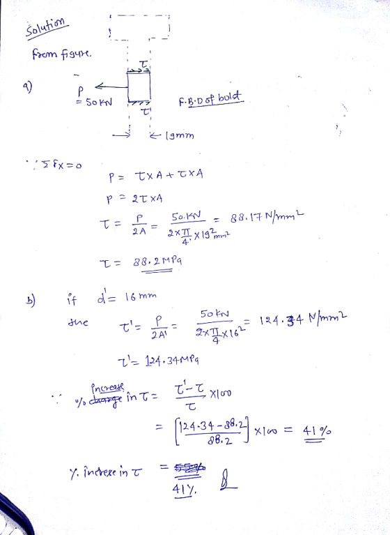
 MECH 3130 NAME: QUIZ 4 SIMPLE CONNECTIONS - FALL 2018 The connection shown below is called a double shear connection because the bolts are supported by two A plates. Plate B is pulled by a force P as shown. Determine the maximum force P that can be applied to the connection if the diameter of each bolt is 8 mm, and the maximum allowable shear stress in the bolt is 100 MPa
Note: Draw Free-body diagrams for all problems Q.1) Two flanged shafts subjected to a torque To...
 Note: Draw Free-body diagrams for all problems Q.1) Two flanged shafts subjected to a torque To 18 kN-m are connected by four 30-mm bolts as shown in figure below. The diameter of the bolt circle is da- 200 mm. Calculate the shear stress in the bolts. To To
A wooden beam is fabricated by bolting together three members. The cross-sectional dimensions are shown. The...
 A wooden beam is fabricated by bolting together three members. The cross-sectional dimensions are shown. The 8-mm-diameter bolts are spaced at intervals of s = 290 mm along the x axis of the beam. If the internal shear force in the beam is V = 9.4 kN, determine the shear stress t in each bolt. Assume b1 = 49 mm, b2 = 49 mm, d1 = 104 mm, d2 = 270 mm. bib2 bi di d2 X Answer: t =...
shown in Figure 2. Two circular disks A and B are welded to the ends of both bars. The disks lie in planes disks A a...
 shown in Figure 2. Two circular disks A and B are welded to the ends of both bars. The disks lie in planes disks A and B subjecting the bars to torsion. If the allowable maximum shear stress is 35 MPa and the allowable rate of twist is 3°/m for both bars, determine the smallest outer diameter (D, and Di) of both bars. The shear modulus of elasticity is 39 GPa to the axes of the bars. Forces 15 kN...
Example 7: Example 8 done on pre 60 KN collar bearing, d = 25 mm collar,...
 Example 7: Example 8 done on pre 60 KN collar bearing, d = 25 mm collar, t = 8 mm 25mm 50mm The collar bearing shown support a load of 60 kN. The diameter of the shaft is 25 mm. The collar has a thickness of 8 mm and an outside diameter of 50 mm Calculate the normal stress, the shear stress and the bearing stress in the bearing. Solution:
A pin-connected beam AC shown in Figure is supported by 1.6m of strut BD. The beam is subjected t...
 A pin-connected beam AC shown in Figure is supported by 1.6m of strut BD. The beam is subjected to uniformly distributed load of 20 kN/m at 2.5m from A and an inclined concentrated load of 30 KN with 30℃ angle at respectively. The beam has a constant cross-sectional area of Abm = 0.004 m2 and the strut has a constant cross sectional area of Ast = 0.002 m2 respectively. The diameter of all pins is 20 mm. I. Determine the resultant...
 For the beam shown below (neglect self-weight of the beam) 16 kN x 8 mm 19 kN 10 kN/m T 2 mm mm A4n - 3 m +3m → a. Draw the shear force and bending moment diagram. 2 mm Section X-X b. For the cross section x-x given, calculate the maximum tensile and compressive bending stress c. For the cross section X-X given, calculate the maximum shear stress
 P6.010 The mechanism shown in the figure is in equilibrium for an applied load of 25 kN. Specifications for the mechanism limit the shear stress in the steel [G82 Ga] shaft BC to 58 MPa, the shear stress in bolt A to 9u MPa, and the vertical defection of joint D to maximum value of 40 mm. Assume that the bearings allow the shaft to rotate freely. Using L-1.200 mm, -115 mm, and b-225 mm, calculate (a) the minimum diameter...
 The lap joint is connected together using a 28 mm diameter bolt. The bolt is made from a material having a shear stress-strain diagrarn that is approximated as shown. (Figure 1) Part A Determine the shear strain developed in the shear plane of the bolt when P = 310 kN. Express your answer using three significant figures. V AEQ11 ? y = radi Submit Request Answer Figure < 1 of 1 Provide Feedback Nex (MP) 525 350 (rad) DOKS 005
 MECH 3130 NAME: QUIZ 4 SIMPLE CONNECTIONS - FALL 2018 The connection shown below is called a double shear connection because the bolts are supported by two A plates. Plate B is pulled by a force P as shown. Determine the maximum force P that can be applied to the connection if the diameter of each bolt is 8 mm, and the maximum allowable shear stress in the bolt is 100 MPa
 Note: Draw Free-body diagrams for all problems Q.1) Two flanged shafts subjected to a torque To 18 kN-m are connected by four 30-mm bolts as shown in figure below. The diameter of the bolt circle is da- 200 mm. Calculate the shear stress in the bolts. To To
 A wooden beam is fabricated by bolting together three members. The cross-sectional dimensions are shown. The 8-mm-diameter bolts are spaced at intervals of s = 290 mm along the x axis of the beam. If the internal shear force in the beam is V = 9.4 kN, determine the shear stress t in each bolt. Assume b1 = 49 mm, b2 = 49 mm, d1 = 104 mm, d2 = 270 mm. bib2 bi di d2 X Answer: t =...
 shown in Figure 2. Two circular disks A and B are welded to the ends of both bars. The disks lie in planes disks A and B subjecting the bars to torsion. If the allowable maximum shear stress is 35 MPa and the allowable rate of twist is 3°/m for both bars, determine the smallest outer diameter (D, and Di) of both bars. The shear modulus of elasticity is 39 GPa to the axes of the bars. Forces 15 kN...
 Example 7: Example 8 done on pre 60 KN collar bearing, d = 25 mm collar, t = 8 mm 25mm 50mm The collar bearing shown support a load of 60 kN. The diameter of the shaft is 25 mm. The collar has a thickness of 8 mm and an outside diameter of 50 mm Calculate the normal stress, the shear stress and the bearing stress in the bearing. Solution:
Most questions answered within 3 hours.
-
Where is the error in this code sequence?
String s1 = "Hello";
String s2 = "ello";...
asked 10 months ago -
Financial data for Joel de Paris, Inc., for last year
follow:
Joel de Paris, Inc.
Balance...
asked 10 months ago -
Consider this reaction:
Al2(SO4)3 (aq)+ BaCl3
(aq) Al2Cl6 (aq)- +
3BaSO4(s) . What is the...
asked 10 months ago -
Suppose that Savneet is considering increasing her
recent random sample from 20 car rentals to 40...
asked 10 months ago -
Trucks arrive at an unloading terminal at an average rate of 120
per hour.
Trucks arrive...
asked 10 months ago -
Why are methanol and ethanol completely soluble in water while
octanol is not very little soluble....
asked 10 months ago -
A facilities manager at a university reads in a research report
that the mean amount of...
asked 10 months ago -
When the CuSO4 is rehydrated by adding water to the anhydrous
compound, is this an endothermic...
asked 10 months ago -
A ray of sunlight is passing from diamond into crown glass; the
angle of incidence is...
asked 10 months ago -
A block of mass 0.249 kg is placed on top of a light, vertical
spring of...
asked 10 months ago -
how do the kidneys compensate in the presences of acidosis
a) trigger hyperventilate
b) reserve acid...
asked 10 months ago -
Question 501 pts
The rental rate of capital to the firm increases. Which of the
following...
asked 10 months ago