
Homework Answers


Add Answer to:
An shown in the folloing figure, shaft A. made of AISI 1020 hot-rolled steelis welded to...
doesn't need any extra information, everything is in there indi 2.. In the figure shown, shaft...
 doesn't need any extra information, everything is in
there
indi 2.. In the figure shown, shaft A, made of AISI 1020 hot-rolled steel, is welded to a fixed support and is subjected to loading by equal and opposite forces F via shaft B. A theoretical stress-concentration factor Kts of 1.6 is induced in the shaft by the -in weld fillet. The length of shaft A from the fixed support to the connection at shaft B is 2 ft. The load...
doesn't need any extra information, everything is in
there
indi 2.. In the figure shown, shaft A, made of AISI 1020 hot-rolled steel, is welded to a fixed support and is subjected to loading by equal and opposite forces F via shaft B. A theoretical stress-concentration factor Kts of 1.6 is induced in the shaft by the -in weld fillet. The length of shaft A from the fixed support to the connection at shaft B is 2 ft. The load...
1. A plate made of AISI 1010 is welded to base plates made of AISI 1020....
 1. A plate made of AISI 1010 is welded to base plates made of AISI 1020. The weld electrode is E60. Calculations show a critical shear stress of 5 ksi. The factor of safety guarding against static failure is: a) 2.82 b) 3.30 c) 3.72 d) 4.41 e) None of these
An U-shaped beam made of AISI 1030 HR steel is welded to the fixed support as shown in the figure.
 An U-shaped beam made of AISI 1030 HR steel is welded to the fixed support as shown in the figure.
The beam is subjected to the load F which is varying between 0 and 2 kN. The load F is applied at the
weld group centroid G. Design the welded joint for the following working conditions:
Reliability : R = 0.9
Safety factor: n=2.5
b = 60 mm, d = 120 mm and L = 200 mm
Take Ssu=0.67Sut
An U-shaped beam made of AISI 1030 HR steel is welded to the fixed support as shown in the figure.
The beam is subjected to the load F which is varying between 0 and 2 kN. The load F is applied at the
weld group centroid G. Design the welded joint for the following working conditions:
Reliability : R = 0.9
Safety factor: n=2.5
b = 60 mm, d = 120 mm and L = 200 mm
Take Ssu=0.67Sut
The shaft shown in the figure is machined from AISI 1040 CD steel and is supported in rolling bearings at A and B.
 The shaft shown in the figure is machined from AISI 1040 CD steel and is supported in rolling bearings at A and B. The applied forces F1 = 1500 lbf and F2 = 3000 lbf are coming off of gears located at respective positions. The shaft rotates at 2000 rpm while transmitting 50hp between the gears. Determine the minimum fatigue factor of safety based on achieving infinite life using Modified- Goodman theory. If infinite life is not predicted, estimate the...
The rotating shaft shown in the figure is machined from AISI 1020 CD steel. It is subjected to a force of F=6 kN.
 Problem 4: The rotating shaft shown in the figure is machined from AISI 1020 CD steel. It is subjected to a force of F=6 kN. Find the maximum factor of safety for fatigue based on infinite life. If the life is not infinite, estimate the number of cycles. Be sure to check for yielding. All dimensions are in mm.
Dont go by the 30mm !! USE the 16!!! A hot rolled AISI 1040 shaft made...
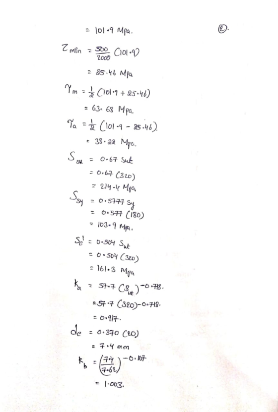
 Dont go by the 30mm !! USE the 16!!!
A hot rolled AISI 1040 shaft made transmits a repeated torque of T=500Nm. The reliability is 50% and the part will be used at room temperature. Find the factor of safety at a section where the diameter is 30mm. Use Goodman criterion T=500Nm 16 mm
Dont go by the 30mm !! USE the 16!!!
A hot rolled AISI 1040 shaft made transmits a repeated torque of T=500Nm. The reliability is 50% and the part will be used at room temperature. Find the factor of safety at a section where the diameter is 30mm. Use Goodman criterion T=500Nm 16 mm
6-16 The rotating shaft shown in the figure is máchined from AISI 1020 CD steel. It...
 6-16 The rotating shaft shown in the figure is máchined from AISI 1020 CD steel. It is subjected o a force of F = 6 kN. Find the minimum factor of safety for fatigue based on infinite life. If the life is not infinite, estimate the number of cycles. Be sure to check for yielding. 500 25 D 35 D 50 D 3 R Problem 6-16 mensions in millimeters 25 D. 20 20 20 20 280
The rotating shaft in the glven figure is machined from AISI 1020 CD steel. It is...
 The rotating shaft in the glven figure is machined from AISI 1020 CD steel. It is subjected to a force of F=7 kN. Find the minimum factor of safety for fatigue based on Infinite life. Be sure to check for yielding. 500 175 23 D. 35 D. -3R. 50 D -23 D. 20 -180 What are the values of the theoretical stress-concentration factor, the notch sensitivity, and the fatigue stress concentration-factor? The value of the theoretical stress-concentration factor is The...
The shaft shown in the figure is machined from AISI 1040 CD steel. The shaft rotates...
 The shaft shown in the figure is machined from AISI 1040 CD steel. The shaft rotates at 1600 rpm and is supported in rolling bearings at A and B. The applied forces are F1 = 1200 lbf and F2 = 2400 lbf. Determine the minimum fatigue factor of safety (nd based on achieving infinite life. If infinite life is not predicted, estimate the number of cycles (M) to failure. Also check for yielding. op - in 8in- F F in]...
The rotating shaft in the glven figure is machined from AISI 1020 CD steel. It is subjected to a force of F= 7 kN.
 The rotating shaft in the glven figure is machined from AISI 1020 CD steel. It is subjected to a force of F= 7 kN. Find the minimum factor of safety for fatigue based on Infinite life. Be sure to check for yielding. What are the values of the theoretical stress-concentration factor, the notch sensitivity. and the fatigue stress concentration-factor? The value of the theoretical stress-concentration factor is _______ The value of the notch sensitivity is _______ The value of the fatigue stress-concentration factor is...
 doesn't need any extra information, everything is in
there
indi 2.. In the figure shown, shaft A, made of AISI 1020 hot-rolled steel, is welded to a fixed support and is subjected to loading by equal and opposite forces F via shaft B. A theoretical stress-concentration factor Kts of 1.6 is induced in the shaft by the -in weld fillet. The length of shaft A from the fixed support to the connection at shaft B is 2 ft. The load...
doesn't need any extra information, everything is in
there
indi 2.. In the figure shown, shaft A, made of AISI 1020 hot-rolled steel, is welded to a fixed support and is subjected to loading by equal and opposite forces F via shaft B. A theoretical stress-concentration factor Kts of 1.6 is induced in the shaft by the -in weld fillet. The length of shaft A from the fixed support to the connection at shaft B is 2 ft. The load...
 1. A plate made of AISI 1010 is welded to base plates made of AISI 1020. The weld electrode is E60. Calculations show a critical shear stress of 5 ksi. The factor of safety guarding against static failure is: a) 2.82 b) 3.30 c) 3.72 d) 4.41 e) None of these
 Dont go by the 30mm !! USE the 16!!!
A hot rolled AISI 1040 shaft made transmits a repeated torque of T=500Nm. The reliability is 50% and the part will be used at room temperature. Find the factor of safety at a section where the diameter is 30mm. Use Goodman criterion T=500Nm 16 mm
Dont go by the 30mm !! USE the 16!!!
A hot rolled AISI 1040 shaft made transmits a repeated torque of T=500Nm. The reliability is 50% and the part will be used at room temperature. Find the factor of safety at a section where the diameter is 30mm. Use Goodman criterion T=500Nm 16 mm
 6-16 The rotating shaft shown in the figure is máchined from AISI 1020 CD steel. It is subjected o a force of F = 6 kN. Find the minimum factor of safety for fatigue based on infinite life. If the life is not infinite, estimate the number of cycles. Be sure to check for yielding. 500 25 D 35 D 50 D 3 R Problem 6-16 mensions in millimeters 25 D. 20 20 20 20 280
 The rotating shaft in the glven figure is machined from AISI 1020 CD steel. It is subjected to a force of F=7 kN. Find the minimum factor of safety for fatigue based on Infinite life. Be sure to check for yielding. 500 175 23 D. 35 D. -3R. 50 D -23 D. 20 -180 What are the values of the theoretical stress-concentration factor, the notch sensitivity, and the fatigue stress concentration-factor? The value of the theoretical stress-concentration factor is The...
 The shaft shown in the figure is machined from AISI 1040 CD steel. The shaft rotates at 1600 rpm and is supported in rolling bearings at A and B. The applied forces are F1 = 1200 lbf and F2 = 2400 lbf. Determine the minimum fatigue factor of safety (nd based on achieving infinite life. If infinite life is not predicted, estimate the number of cycles (M) to failure. Also check for yielding. op - in 8in- F F in]...
Most questions answered within 3 hours.
-
Where is the error in this code sequence?
String s1 = "Hello";
String s2 = "ello";...
asked 11 months ago -
Financial data for Joel de Paris, Inc., for last year
follow:
Joel de Paris, Inc.
Balance...
asked 11 months ago -
Consider this reaction:
Al2(SO4)3 (aq)+ BaCl3
(aq) Al2Cl6 (aq)- +
3BaSO4(s) . What is the...
asked 11 months ago -
Suppose that Savneet is considering increasing her
recent random sample from 20 car rentals to 40...
asked 11 months ago -
Trucks arrive at an unloading terminal at an average rate of 120
per hour.
Trucks arrive...
asked 11 months ago -
Why are methanol and ethanol completely soluble in water while
octanol is not very little soluble....
asked 11 months ago -
A facilities manager at a university reads in a research report
that the mean amount of...
asked 11 months ago -
When the CuSO4 is rehydrated by adding water to the anhydrous
compound, is this an endothermic...
asked 11 months ago -
A ray of sunlight is passing from diamond into crown glass; the
angle of incidence is...
asked 11 months ago -
A block of mass 0.249 kg is placed on top of a light, vertical
spring of...
asked 11 months ago -
how do the kidneys compensate in the presences of acidosis
a) trigger hyperventilate
b) reserve acid...
asked 11 months ago -
Question 501 pts
The rental rate of capital to the firm increases. Which of the
following...
asked 11 months ago