
Homework Answers


Add Answer to:
AISI 1018 HR
Section #2 (80p) 035 CD 1018 HR Q1. The figure shows a shaft...
The figure shows a shaft mounted in bearings at A and D and having pulleys at B and C. The forces shown acting on the pully surfaces represent the belt tensions.
 Problem 1: The figure shows a shaft mounted in bearings at A and D and having pulleys at B and C. The forces shown acting on the pully surfaces represent the belt tensions. The shaft is to be made of AISI 1040 HR steel. Using a conservative failure theory with a design factor of 2, determine the minimum shaft diameter to avoid yielding.
The figure shows a 1.5 inch diameter shaft mounted in bearings at A and D and...
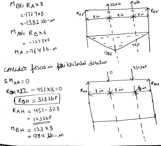
 The figure shows a 1.5 inch diameter shaft mounted in bearings at A and D and having pulleys at B and C. The forces shown acting on the pulley surfaces represent the belt tensions. Considering static loading, determine the principal stresses in the shaft? 6-in D. 300 lbf 50 lbf 27 lbf 360 lbfID 8-in D.6 in B8 in A 8 in
A countershaft, made of AISI 1035 CD steel, carrying two V-belt pulleys is shown in the figure. P...
 A countershaft, made of AISI 1035 CD steel, carrying two V-belt pulleys is shown in the figure. Pulley A receives power from a motor through a belt with the belt tensions shown. The power is transmitted through the shaft and delivered to the belt on pulley B. Assume the belt tension on the loose side at B is 25 percent of the tension on the tight side (F2 - 0.25 F) 1) Based on the equations for yielding conditions discussed...
The figure above shows a shaft mounted in bearings A and D and having pulleys at B and C.
 The figure above shows a shaft mounted in bearings A and D and having pulleys at B and C. The shaft is 20 mm in diameter and made of AISI 1020 CD steel. The forces shown acting on the pulley surfaces represent the belt tensions. The shaft is concerned with yielding and fatigue failure. [Stress analysis) (1) Draw the free body diagrams and find reaction forces at A and D in the xy and xz planes. (2) Draw the shear force and moment...
Required information The figure shows a shaft mounted in bearings at A and D and having...
 Required information The figure shows a shaft mounted in bearings at A and D and having pulleys at B and C. The forces shown acting on the pulley surfaces represent the belt tensions. The shaft is to be made of AISI 1035 CD steel. The design factor is 2. The value of FB1= 240 lb, FB2= 40 lb, FC1= 47.256 lb, and Fc2= 313.974 lb. NOTE: This is a multi-part question. Once an answer is submitted, you will be unable...
The shaft shown in the figure is machined from AISI 1040 CD steel and is supported in rolling bearings at A and B.
 The shaft shown in the figure is machined from AISI 1040 CD steel and is supported in rolling bearings at A and B. The applied forces F1 = 1500 lbf and F2 = 3000 lbf are coming off of gears located at respective positions. The shaft rotates at 2000 rpm while transmitting 50hp between the gears. Determine the minimum fatigue factor of safety based on achieving infinite life using Modified- Goodman theory. If infinite life is not predicted, estimate the...
 The figure shows a 1.5 inch diameter shaft mounted in bearings at A and D and having pulleys at B and C. The forces shown acting on the pulley surfaces represent the belt tensions. Considering static loading, determine the principal stresses in the shaft? 6-in D. 300 lbf 50 lbf 27 lbf 360 lbfID 8-in D.6 in B8 in A 8 in
 A countershaft, made of AISI 1035 CD steel, carrying two V-belt pulleys is shown in the figure. Pulley A receives power from a motor through a belt with the belt tensions shown. The power is transmitted through the shaft and delivered to the belt on pulley B. Assume the belt tension on the loose side at B is 25 percent of the tension on the tight side (F2 - 0.25 F) 1) Based on the equations for yielding conditions discussed...
 Required information The figure shows a shaft mounted in bearings at A and D and having pulleys at B and C. The forces shown acting on the pulley surfaces represent the belt tensions. The shaft is to be made of AISI 1035 CD steel. The design factor is 2. The value of FB1= 240 lb, FB2= 40 lb, FC1= 47.256 lb, and Fc2= 313.974 lb. NOTE: This is a multi-part question. Once an answer is submitted, you will be unable...
Most questions answered within 3 hours.
-
Where is the error in this code sequence?
String s1 = "Hello";
String s2 = "ello";...
asked 11 months ago -
Financial data for Joel de Paris, Inc., for last year
follow:
Joel de Paris, Inc.
Balance...
asked 11 months ago -
Consider this reaction:
Al2(SO4)3 (aq)+ BaCl3
(aq) Al2Cl6 (aq)- +
3BaSO4(s) . What is the...
asked 11 months ago -
Suppose that Savneet is considering increasing her
recent random sample from 20 car rentals to 40...
asked 11 months ago -
Trucks arrive at an unloading terminal at an average rate of 120
per hour.
Trucks arrive...
asked 11 months ago -
Why are methanol and ethanol completely soluble in water while
octanol is not very little soluble....
asked 11 months ago -
A facilities manager at a university reads in a research report
that the mean amount of...
asked 11 months ago -
When the CuSO4 is rehydrated by adding water to the anhydrous
compound, is this an endothermic...
asked 11 months ago -
A ray of sunlight is passing from diamond into crown glass; the
angle of incidence is...
asked 11 months ago -
A block of mass 0.249 kg is placed on top of a light, vertical
spring of...
asked 11 months ago -
how do the kidneys compensate in the presences of acidosis
a) trigger hyperventilate
b) reserve acid...
asked 11 months ago -
Question 501 pts
The rental rate of capital to the firm increases. Which of the
following...
asked 11 months ago