


Homework Answers
Add Answer to:
please only answer Part C, all other parts is for any
information you may need.
-...
During this term, you have studied inductors and capacitors, as well as the basics of ac,...
During this term, you have studied inductors and capacitors, as well as the basics of ac, test equipment, and the effects of reactance, impedance, and resonance. Based on that knowledge and experimentation, answer the following practical application questions. Describe the physical characteristics of a basic inductor. Describe the physical characteristics of a basic capacitor. If an oscilloscope shows a 20 Vpp sine wave, how would you determine the rms value? Calculate what that Vrms value would be. What is the...
Learning Goal: To understand the use of phasor diagrams in calculating the impedance and resonance conditions in a seri...
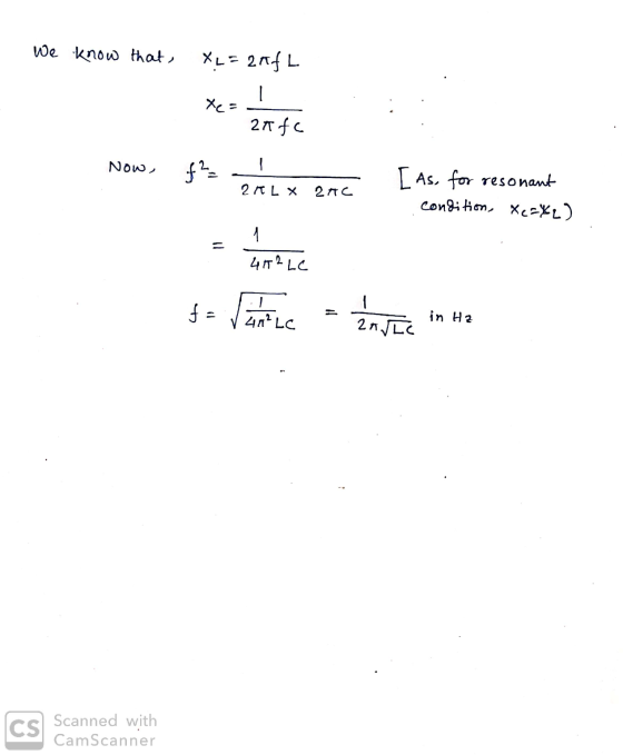
 Learning Goal: To understand the use of phasor diagrams in calculating the impedance and resonance conditions in a series L-R-C circuit. At resonance, XL = Xc. The voltage across the capacitor exactly cancels that across the i have the same amplitude. Thus, the inductor and capacitor effectively cancel out in the formu not come as a surprise that the resonant frequency equals the natural frequency of the oscilla In this problem, you will consider a series L-R-C circuit, containing a...
Will give an up vote only if all parts are answered and detailed explanations are given....
 Will give an up vote only if all parts are answered and detailed
explanations are given. Thank you.
5. (26 points) For the LRC circuit driven, not in resonance, by an AC generator depicted below, C = 40 uF, L = 90 mH & R=80 S2. Use the relative magnitudes of the effective resistance values of each component to determine the values for your diagram. The generator is a typical one used in the U.S. with a peak voltage of...
Will give an up vote only if all parts are answered and detailed
explanations are given. Thank you.
5. (26 points) For the LRC circuit driven, not in resonance, by an AC generator depicted below, C = 40 uF, L = 90 mH & R=80 S2. Use the relative magnitudes of the effective resistance values of each component to determine the values for your diagram. The generator is a typical one used in the U.S. with a peak voltage of...
A resistance R = 10Ω, a capacitor C = 15μF, an inductor of L = 38mH,...
A resistance R = 10Ω, a capacitor C = 15μF, an inductor of L = 38mH, and an alternating current source with a voltage amplitude of 50V to 160Hz are connected in series. A- Calculate the angular frequency of the source B- Calculate the XL, XC, and Z impedance reactances C- Calculate the lag between the circuit current and the source voltage D- Calculate the amplitude of the circuit current and express the circuit current as a function of time...
A continuous AC voltage with peak voltage of 6 V and frequency f=732398 Hz is connected...
 A continuous AC voltage with peak voltage of 6 V and frequency f=732398 Hz is connected with a resistor (R-220 Ω), a capacitor with C-0.1 μΕ and an an inductor with L=680 nH. What is the capacitive reactance? What is the inductive reactance? What is the impedance when all three components are connected in SERIES? What is the current when all three components are connected in SERIES? What is the impedance of the circuit when all three components are connected...
Help A series RLC circuit has components with the following values: L = 16.0 mH. C...
 Help
A series RLC circuit has components with the following values: L = 16.0 mH. C = 82.0 nF, R = 15.0 ohm, and Delta V_max = 100 V, with Delta v = Delta V_max sin omega t. Find the resonant frequency of the circuit. 4.3939e03 Resonance occurs when the impedance is at a minimum. kHz Find the amplitude of the current at the resonant frequency. 6.67 A Find the Q of the circuit. 2.68 How is the Q related...
Help
A series RLC circuit has components with the following values: L = 16.0 mH. C = 82.0 nF, R = 15.0 ohm, and Delta V_max = 100 V, with Delta v = Delta V_max sin omega t. Find the resonant frequency of the circuit. 4.3939e03 Resonance occurs when the impedance is at a minimum. kHz Find the amplitude of the current at the resonant frequency. 6.67 A Find the Q of the circuit. 2.68 How is the Q related...
multisim help Part II: Capacitors in AC Circuits In this part, you will determine the impedance...
 multisim help
Part II: Capacitors in AC Circuits In this part, you will determine the impedance of the circuit at various frequencies. The capacitive reactance is calculated using Xc = Vc/Ic 1- Construct the circuit of Figure 9.2. Connect meters to measure voltage and current. R1 mA 1kohm C1 AC 3.3uF Figure 9.2-Circuit to Determine Capacitive Reactance 2- Set the voltage to 6Vrms at 60Hz. Measure and record values in Table 9.3. Calculate reactance using Xc = 1/(2nf C) and...
multisim help
Part II: Capacitors in AC Circuits In this part, you will determine the impedance of the circuit at various frequencies. The capacitive reactance is calculated using Xc = Vc/Ic 1- Construct the circuit of Figure 9.2. Connect meters to measure voltage and current. R1 mA 1kohm C1 AC 3.3uF Figure 9.2-Circuit to Determine Capacitive Reactance 2- Set the voltage to 6Vrms at 60Hz. Measure and record values in Table 9.3. Calculate reactance using Xc = 1/(2nf C) and...
Need help with part d please An RLC series circuit has a 5.000, a 20.00mH inductor,...
 Need help with part d please
An RLC series circuit has a 5.000, a 20.00mH inductor, and a 30.00uF capacitor, and has a 110V source. a. Find the circuit's impedance at 60 Hz. b. What is the current at the 60Hz frequency? c. What is the resonant frequency of the circuit? d. What is the average power dissipated at the circuit's resonance frequency?
Need help with part d please
An RLC series circuit has a 5.000, a 20.00mH inductor, and a 30.00uF capacitor, and has a 110V source. a. Find the circuit's impedance at 60 Hz. b. What is the current at the 60Hz frequency? c. What is the resonant frequency of the circuit? d. What is the average power dissipated at the circuit's resonance frequency?
1 ) A series circuit consisted of R= 10 KΩ, L= 42 mH , C= 2.1...
 1 ) A series circuit consisted of R= 10 KΩ, L= 42 mH , C= 2.1 µF
is connected to an alternative voltage with maximum voltage of
Vm = 24 V and frequency of 300.0 Hz.
Find the following:
Show the formula for each question. Show your
Calculations – put result in a box with its unit. Please write your
answer under each question
a)Find the value of angular frequency ω .
b) Inductive Reactance ( XL)
c)Capacitive Reactance (...
1 ) A series circuit consisted of R= 10 KΩ, L= 42 mH , C= 2.1 µF
is connected to an alternative voltage with maximum voltage of
Vm = 24 V and frequency of 300.0 Hz.
Find the following:
Show the formula for each question. Show your
Calculations – put result in a box with its unit. Please write your
answer under each question
a)Find the value of angular frequency ω .
b) Inductive Reactance ( XL)
c)Capacitive Reactance (...
1. From Figure 9-2 and the equations above choose which plot best describes the impedance due...
 1. From Figure 9-2 and the equations above choose which
plot best describes the impedance due to:
a. A Resistor
b. A Capacitor
PART 1: IMPEDANCE OF A CAPACITOR PREPARATION In an AC circuit capacitors and inductors have an effective resistance that restricts the flow of current, this is known as impedance. An equivalent to Ohm's law can be written where resistance R is replaced by the impedance Z: V = 12 (9-4) where V and I are either...
1. From Figure 9-2 and the equations above choose which
plot best describes the impedance due to:
a. A Resistor
b. A Capacitor
PART 1: IMPEDANCE OF A CAPACITOR PREPARATION In an AC circuit capacitors and inductors have an effective resistance that restricts the flow of current, this is known as impedance. An equivalent to Ohm's law can be written where resistance R is replaced by the impedance Z: V = 12 (9-4) where V and I are either...
 Learning Goal: To understand the use of phasor diagrams in calculating the impedance and resonance conditions in a series L-R-C circuit. At resonance, XL = Xc. The voltage across the capacitor exactly cancels that across the i have the same amplitude. Thus, the inductor and capacitor effectively cancel out in the formu not come as a surprise that the resonant frequency equals the natural frequency of the oscilla In this problem, you will consider a series L-R-C circuit, containing a...
 Will give an up vote only if all parts are answered and detailed
explanations are given. Thank you.
5. (26 points) For the LRC circuit driven, not in resonance, by an AC generator depicted below, C = 40 uF, L = 90 mH & R=80 S2. Use the relative magnitudes of the effective resistance values of each component to determine the values for your diagram. The generator is a typical one used in the U.S. with a peak voltage of...
Will give an up vote only if all parts are answered and detailed
explanations are given. Thank you.
5. (26 points) For the LRC circuit driven, not in resonance, by an AC generator depicted below, C = 40 uF, L = 90 mH & R=80 S2. Use the relative magnitudes of the effective resistance values of each component to determine the values for your diagram. The generator is a typical one used in the U.S. with a peak voltage of...
 A continuous AC voltage with peak voltage of 6 V and frequency f=732398 Hz is connected with a resistor (R-220 Ω), a capacitor with C-0.1 μΕ and an an inductor with L=680 nH. What is the capacitive reactance? What is the inductive reactance? What is the impedance when all three components are connected in SERIES? What is the current when all three components are connected in SERIES? What is the impedance of the circuit when all three components are connected...
 Help
A series RLC circuit has components with the following values: L = 16.0 mH. C = 82.0 nF, R = 15.0 ohm, and Delta V_max = 100 V, with Delta v = Delta V_max sin omega t. Find the resonant frequency of the circuit. 4.3939e03 Resonance occurs when the impedance is at a minimum. kHz Find the amplitude of the current at the resonant frequency. 6.67 A Find the Q of the circuit. 2.68 How is the Q related...
Help
A series RLC circuit has components with the following values: L = 16.0 mH. C = 82.0 nF, R = 15.0 ohm, and Delta V_max = 100 V, with Delta v = Delta V_max sin omega t. Find the resonant frequency of the circuit. 4.3939e03 Resonance occurs when the impedance is at a minimum. kHz Find the amplitude of the current at the resonant frequency. 6.67 A Find the Q of the circuit. 2.68 How is the Q related...
 multisim help
Part II: Capacitors in AC Circuits In this part, you will determine the impedance of the circuit at various frequencies. The capacitive reactance is calculated using Xc = Vc/Ic 1- Construct the circuit of Figure 9.2. Connect meters to measure voltage and current. R1 mA 1kohm C1 AC 3.3uF Figure 9.2-Circuit to Determine Capacitive Reactance 2- Set the voltage to 6Vrms at 60Hz. Measure and record values in Table 9.3. Calculate reactance using Xc = 1/(2nf C) and...
multisim help
Part II: Capacitors in AC Circuits In this part, you will determine the impedance of the circuit at various frequencies. The capacitive reactance is calculated using Xc = Vc/Ic 1- Construct the circuit of Figure 9.2. Connect meters to measure voltage and current. R1 mA 1kohm C1 AC 3.3uF Figure 9.2-Circuit to Determine Capacitive Reactance 2- Set the voltage to 6Vrms at 60Hz. Measure and record values in Table 9.3. Calculate reactance using Xc = 1/(2nf C) and...
 Need help with part d please
An RLC series circuit has a 5.000, a 20.00mH inductor, and a 30.00uF capacitor, and has a 110V source. a. Find the circuit's impedance at 60 Hz. b. What is the current at the 60Hz frequency? c. What is the resonant frequency of the circuit? d. What is the average power dissipated at the circuit's resonance frequency?
Need help with part d please
An RLC series circuit has a 5.000, a 20.00mH inductor, and a 30.00uF capacitor, and has a 110V source. a. Find the circuit's impedance at 60 Hz. b. What is the current at the 60Hz frequency? c. What is the resonant frequency of the circuit? d. What is the average power dissipated at the circuit's resonance frequency?
 1 ) A series circuit consisted of R= 10 KΩ, L= 42 mH , C= 2.1 µF
is connected to an alternative voltage with maximum voltage of
Vm = 24 V and frequency of 300.0 Hz.
Find the following:
Show the formula for each question. Show your
Calculations – put result in a box with its unit. Please write your
answer under each question
a)Find the value of angular frequency ω .
b) Inductive Reactance ( XL)
c)Capacitive Reactance (...
1 ) A series circuit consisted of R= 10 KΩ, L= 42 mH , C= 2.1 µF
is connected to an alternative voltage with maximum voltage of
Vm = 24 V and frequency of 300.0 Hz.
Find the following:
Show the formula for each question. Show your
Calculations – put result in a box with its unit. Please write your
answer under each question
a)Find the value of angular frequency ω .
b) Inductive Reactance ( XL)
c)Capacitive Reactance (...
 1. From Figure 9-2 and the equations above choose which
plot best describes the impedance due to:
a. A Resistor
b. A Capacitor
PART 1: IMPEDANCE OF A CAPACITOR PREPARATION In an AC circuit capacitors and inductors have an effective resistance that restricts the flow of current, this is known as impedance. An equivalent to Ohm's law can be written where resistance R is replaced by the impedance Z: V = 12 (9-4) where V and I are either...
1. From Figure 9-2 and the equations above choose which
plot best describes the impedance due to:
a. A Resistor
b. A Capacitor
PART 1: IMPEDANCE OF A CAPACITOR PREPARATION In an AC circuit capacitors and inductors have an effective resistance that restricts the flow of current, this is known as impedance. An equivalent to Ohm's law can be written where resistance R is replaced by the impedance Z: V = 12 (9-4) where V and I are either...
Most questions answered within 3 hours.
-
Where is the error in this code sequence?
String s1 = "Hello";
String s2 = "ello";...
asked 10 months ago -
Financial data for Joel de Paris, Inc., for last year
follow:
Joel de Paris, Inc.
Balance...
asked 10 months ago -
Consider this reaction:
Al2(SO4)3 (aq)+ BaCl3
(aq) Al2Cl6 (aq)- +
3BaSO4(s) . What is the...
asked 10 months ago -
Suppose that Savneet is considering increasing her
recent random sample from 20 car rentals to 40...
asked 10 months ago -
Trucks arrive at an unloading terminal at an average rate of 120
per hour.
Trucks arrive...
asked 10 months ago -
Why are methanol and ethanol completely soluble in water while
octanol is not very little soluble....
asked 10 months ago -
A facilities manager at a university reads in a research report
that the mean amount of...
asked 10 months ago -
When the CuSO4 is rehydrated by adding water to the anhydrous
compound, is this an endothermic...
asked 10 months ago -
A ray of sunlight is passing from diamond into crown glass; the
angle of incidence is...
asked 10 months ago -
A block of mass 0.249 kg is placed on top of a light, vertical
spring of...
asked 10 months ago -
how do the kidneys compensate in the presences of acidosis
a) trigger hyperventilate
b) reserve acid...
asked 10 months ago -
Question 501 pts
The rental rate of capital to the firm increases. Which of the
following...
asked 10 months ago