
Homework Answers

Add Answer to:
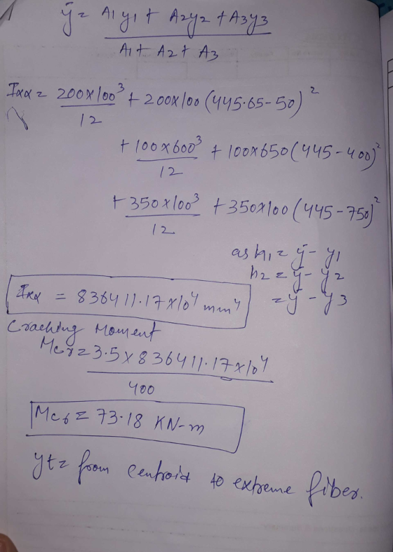
1. For the doubly section shown in Figure, determine the cracking moments iff-25 MPa. 100 600...
Figure 1 shows the cross section of a lipped channel. The cross section carries a shear...
 Figure 1 shows the cross section of a lipped channel. The cross section carries a shear force of 250 kN acting at 45° below the major principal axis (as shown) and through the shear centre. Determine the Ans: 134.1 MPa) maximum shear stress. (Use line of mid-thickness properties) t 45 34 S.C 250 N たA 100 Figure
7. Evaluate M, for the section shown in Figure 3.9(2). Assume f = 20 MPa. 200...
 7. Evaluate M, for the section shown in Figure 3.9(2). Assume f = 20 MPa. 200 t 100 @ 2 N24 500 4 N24 1001 Figure 3.9(2) Cross-sectional details of the example beam section Note: all dimensions are in mm.
1) The allowable bending strength in A-A cross section is Oallow= 150 MPa. Determine the maximum...
 1) The allowable bending strength in A-A cross section is Oallow= 150 MPa. Determine the maximum load P where it applied to the bar from point E (40 points). Figure 1 D 600 mm a 300 mm 20 mm В. 50 mm 25 mm 25 mm 25 mm A-A cross section
WORKING with Plates-PLATE#3 3. For the cross-section shown in Figure 3, (a) determine the bending moment...
 WORKING with Plates-PLATE#3 3. For the cross-section shown in Figure 3, (a) determine the bending moment that the reinforced concrete section can cary If As 1200 mm2. (b) determine the maximum area of steel that can be used In this section and (c) determine the maximum moment that can be resisted by the section. Use Fc 25 MPa, fy 400 Mpa 250 HGURE uaugo9-p
5. Determine the mid-span short-term deflection of a simply supported beam with the section shown in...
 5. Determine the mid-span short-term deflection of a simply supported beam with the section shown in Figure Q5. Design data: Concrete strength: fcu 30 MPa. Area of tensile steel reinforcement: As 1500 mm Area of compressive steel reinforcement: A,-1500 mm2 Instantaneous static modulus of elasticity of concrete = 25GPa. Span -8.0 m Loading: Dead load 5.0 kN/m (uniformly distributed load); Live load 5.0 kN/m (uniformly distributed load) (Hint: the height of neutral axis of the mid-span section under the service...
A beam with cross-section as shown in Figure 2(a) is made of an elasto-plastic material. The...
 A beam with cross-section as shown in Figure 2(a) is made of an
elasto-plastic material. The stressstrain relationship of the
material is as shown in Figure 2(b): (a) A bending moment is
applied to this section and increased until the entire top flange
yielded. Calculate the magnitude of the moment at this stage of
loading. (b) Determine the yield moment of the beam (c) Determine
the ultimate moment capacity of the beam (d) Determine the shape
factor of the beam...
A beam with cross-section as shown in Figure 2(a) is made of an
elasto-plastic material. The stressstrain relationship of the
material is as shown in Figure 2(b): (a) A bending moment is
applied to this section and increased until the entire top flange
yielded. Calculate the magnitude of the moment at this stage of
loading. (b) Determine the yield moment of the beam (c) Determine
the ultimate moment capacity of the beam (d) Determine the shape
factor of the beam...
Q5 Consider an extruded aluminium machine part that has the cross-section shown in the accompanying figure....
 Q5 Consider an extruded aluminium machine part that has the cross-section shown in the accompanying figure. Determine the maximum moment M that can be applied to the member if the allowable bending stresses in tension and compression are 200 MPa and 100 MPa respectively 100 mm 25 mm NA 50 mm 25 mm 50 mm 25 mm
Figure 1 shows the cross section of a lipped channel. The cross section carries a shear force of ...
 Figure 1 shows the cross section of a lipped channel. The cross section carries a shear force of 250 kN acting at 45° below the major principal axis (as shown) and through the shear centre. Determine the (Ans: 134.1 MPa) maximum shear stress. (Use line of mid-thickness properties) た45 S.c 4250 N たA 100 Figure 1
Figure 1 shows the cross section of a lipped channel. The cross section carries a shear force of 250 kN acting at 45° below...
Figure 1 shows the cross section of a lipped channel. The cross section carries a shear force of 250 kN acting at 45° below the major principal axis (as shown) and through the shear centre. Determine the (Ans: 134.1 MPa) maximum shear stress. (Use line of mid-thickness properties) た45 S.c 4250 N たA 100 Figure 1
Figure 1 shows the cross section of a lipped channel. The cross section carries a shear force of 250 kN acting at 45° below...
3- Determine the maximum shear stress in the beam section shown in the figure. Determine also...
 3- Determine the maximum shear stress in the beam section shown in the figure. Determine also the rate of twist of the beam section if the shear modulus G is 25 GPa. 100 mm T-25 N.m 3 mm 3 mm 50 mm 80 mm 2 mm
3- Determine the maximum shear stress in the beam section shown in the figure. Determine also the rate of twist of the beam section if the shear modulus G is 25 GPa. 100 mm...
3- Determine the maximum shear stress in the beam section shown in the figure. Determine also the rate of twist of the beam section if the shear modulus G is 25 GPa. 100 mm T-25 N.m 3 mm 3 mm 50 mm 80 mm 2 mm
3- Determine the maximum shear stress in the beam section shown in the figure. Determine also the rate of twist of the beam section if the shear modulus G is 25 GPa. 100 mm...
For the section and material properties shown in Figure 1, calculate the moment and corresponding curvature...
 For the section and material properties shown in Figure 1, calculate the moment and corresponding curvature given a compressive strain at the top fibre of 0.0036 and a neutral axis depth of 48 mm. [6 marks] Perform only one iteration regardless of convergence. 0.0036 E 25 mm 48 mm 220 mm 325 mm 350 mm 675 mm You 250 mm E = 200 GPS Es - 7500 MPa f = 500 MPa f = 40 MPa E = 0.0018 &...
 Figure 1 shows the cross section of a lipped channel. The cross section carries a shear force of 250 kN acting at 45° below the major principal axis (as shown) and through the shear centre. Determine the Ans: 134.1 MPa) maximum shear stress. (Use line of mid-thickness properties) t 45 34 S.C 250 N たA 100 Figure
 7. Evaluate M, for the section shown in Figure 3.9(2). Assume f = 20 MPa. 200 t 100 @ 2 N24 500 4 N24 1001 Figure 3.9(2) Cross-sectional details of the example beam section Note: all dimensions are in mm.
 1) The allowable bending strength in A-A cross section is Oallow= 150 MPa. Determine the maximum load P where it applied to the bar from point E (40 points). Figure 1 D 600 mm a 300 mm 20 mm В. 50 mm 25 mm 25 mm 25 mm A-A cross section
 WORKING with Plates-PLATE#3 3. For the cross-section shown in Figure 3, (a) determine the bending moment that the reinforced concrete section can cary If As 1200 mm2. (b) determine the maximum area of steel that can be used In this section and (c) determine the maximum moment that can be resisted by the section. Use Fc 25 MPa, fy 400 Mpa 250 HGURE uaugo9-p
 5. Determine the mid-span short-term deflection of a simply supported beam with the section shown in Figure Q5. Design data: Concrete strength: fcu 30 MPa. Area of tensile steel reinforcement: As 1500 mm Area of compressive steel reinforcement: A,-1500 mm2 Instantaneous static modulus of elasticity of concrete = 25GPa. Span -8.0 m Loading: Dead load 5.0 kN/m (uniformly distributed load); Live load 5.0 kN/m (uniformly distributed load) (Hint: the height of neutral axis of the mid-span section under the service...
 A beam with cross-section as shown in Figure 2(a) is made of an
elasto-plastic material. The stressstrain relationship of the
material is as shown in Figure 2(b): (a) A bending moment is
applied to this section and increased until the entire top flange
yielded. Calculate the magnitude of the moment at this stage of
loading. (b) Determine the yield moment of the beam (c) Determine
the ultimate moment capacity of the beam (d) Determine the shape
factor of the beam...
A beam with cross-section as shown in Figure 2(a) is made of an
elasto-plastic material. The stressstrain relationship of the
material is as shown in Figure 2(b): (a) A bending moment is
applied to this section and increased until the entire top flange
yielded. Calculate the magnitude of the moment at this stage of
loading. (b) Determine the yield moment of the beam (c) Determine
the ultimate moment capacity of the beam (d) Determine the shape
factor of the beam...
 Q5 Consider an extruded aluminium machine part that has the cross-section shown in the accompanying figure. Determine the maximum moment M that can be applied to the member if the allowable bending stresses in tension and compression are 200 MPa and 100 MPa respectively 100 mm 25 mm NA 50 mm 25 mm 50 mm 25 mm
 Figure 1 shows the cross section of a lipped channel. The cross section carries a shear force of 250 kN acting at 45° below the major principal axis (as shown) and through the shear centre. Determine the (Ans: 134.1 MPa) maximum shear stress. (Use line of mid-thickness properties) た45 S.c 4250 N たA 100 Figure 1
Figure 1 shows the cross section of a lipped channel. The cross section carries a shear force of 250 kN acting at 45° below...
Figure 1 shows the cross section of a lipped channel. The cross section carries a shear force of 250 kN acting at 45° below the major principal axis (as shown) and through the shear centre. Determine the (Ans: 134.1 MPa) maximum shear stress. (Use line of mid-thickness properties) た45 S.c 4250 N たA 100 Figure 1
Figure 1 shows the cross section of a lipped channel. The cross section carries a shear force of 250 kN acting at 45° below...
 3- Determine the maximum shear stress in the beam section shown in the figure. Determine also the rate of twist of the beam section if the shear modulus G is 25 GPa. 100 mm T-25 N.m 3 mm 3 mm 50 mm 80 mm 2 mm
3- Determine the maximum shear stress in the beam section shown in the figure. Determine also the rate of twist of the beam section if the shear modulus G is 25 GPa. 100 mm...
3- Determine the maximum shear stress in the beam section shown in the figure. Determine also the rate of twist of the beam section if the shear modulus G is 25 GPa. 100 mm T-25 N.m 3 mm 3 mm 50 mm 80 mm 2 mm
3- Determine the maximum shear stress in the beam section shown in the figure. Determine also the rate of twist of the beam section if the shear modulus G is 25 GPa. 100 mm...
 For the section and material properties shown in Figure 1, calculate the moment and corresponding curvature given a compressive strain at the top fibre of 0.0036 and a neutral axis depth of 48 mm. [6 marks] Perform only one iteration regardless of convergence. 0.0036 E 25 mm 48 mm 220 mm 325 mm 350 mm 675 mm You 250 mm E = 200 GPS Es - 7500 MPa f = 500 MPa f = 40 MPa E = 0.0018 &...
Most questions answered within 3 hours.
-
Where is the error in this code sequence?
String s1 = "Hello";
String s2 = "ello";...
asked 10 months ago -
Financial data for Joel de Paris, Inc., for last year
follow:
Joel de Paris, Inc.
Balance...
asked 10 months ago -
Consider this reaction:
Al2(SO4)3 (aq)+ BaCl3
(aq) Al2Cl6 (aq)- +
3BaSO4(s) . What is the...
asked 10 months ago -
Suppose that Savneet is considering increasing her
recent random sample from 20 car rentals to 40...
asked 10 months ago -
Trucks arrive at an unloading terminal at an average rate of 120
per hour.
Trucks arrive...
asked 10 months ago -
Why are methanol and ethanol completely soluble in water while
octanol is not very little soluble....
asked 10 months ago -
A facilities manager at a university reads in a research report
that the mean amount of...
asked 10 months ago -
When the CuSO4 is rehydrated by adding water to the anhydrous
compound, is this an endothermic...
asked 10 months ago -
A ray of sunlight is passing from diamond into crown glass; the
angle of incidence is...
asked 10 months ago -
A block of mass 0.249 kg is placed on top of a light, vertical
spring of...
asked 10 months ago -
how do the kidneys compensate in the presences of acidosis
a) trigger hyperventilate
b) reserve acid...
asked 10 months ago -
Question 501 pts
The rental rate of capital to the firm increases. Which of the
following...
asked 10 months ago