
Homework Answers
Add Answer to:
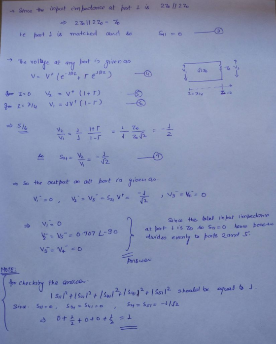
7.32 For the symmetric hybrid shown below, calculate the output voltages if port 1 is fed...
4. A CMOS port output is modelled as shown in Figure 3.4(b). It is powered from...
4. A CMOS port output is modelled as shown in Figure 3.4(b). It is powered from 5V. The value of RS(high) is estimated to be 120 U and the value of RS(low) 70 U. One port pin will light an LED when it is at Logic 1, and another will light an LED when it is at Logic 0. An LED current of 4 mA is required; for this the LEDs have a forward voltage of 1.8 V. Sketch a...
Aufilo polasi For the op amp shown below, the output saturation voltages of the op amp...
 Aufilo polasi For the op amp shown below, the output saturation voltages of the op amp shown below is t 10 volts. In addition, assume that conducting 6. ( 16 points) the a conducting diode has a voltage drop of 0.7 volts. Furthermore, R- R-10 KQ (a) Ir v1.SV, find and v (b) If v, =-2.5 V, find Vo and va
Vcc 12V Q1a Q1b VBIAS Q2 out Output Port Consider the current source circuit shown above. Assume ...
 Vcc 12V Q1a Q1b VBIAS Q2 out Output Port Consider the current source circuit shown above. Assume that the DC bias voltage VBIAs is adjusted so that all transistors are guaranteed to be in the FA Problem 4 (6 points): Calculate the output current, assuming β and VA>oo. Note: you can assume that the output port is grounded for this calculation. [HA Problem 5 (6 points): Calculate the small-signal output resistance of the current source (Rout), assuming β-100 and V,-100V....
1. Find the expression for the output voltage Vou for the circuit shown below in terms...
 1. Find the expression for the output voltage Vou for the circuit shown below in terms of the resistors Ri, R, R and Rs and the input voltages Vi. V2 and V Calculate Vout when R.-R: = R.-1? and R.-10kfand V, = 4nnV, V,-5mV and V,-6m1V. N3. 2. Find the expression for the output voltage in the circuit shown below and calculate the output voltage Vou where R-R-2.2 k2 and R R-10kQ. V-4 V and V the output voltage when...
Use the Method Below 1. Use the method presented in lecture (matched source on one side; matched load on the other) to...
 Use the Method Below
1. Use the method presented in lecture (matched source on one side; matched load on the other) to determine the scattering parameters of the normalized two-port circuit below. Calculate the scattering parameters of the circuit below when used in a 50 2 system 50 Ω 100 Ω Sol: we first normalize the impedance values of the circuit to 50 Ω . To find the scattering parameters Si and S1, attach a matched source to port 1...
Use the Method Below
1. Use the method presented in lecture (matched source on one side; matched load on the other) to determine the scattering parameters of the normalized two-port circuit below. Calculate the scattering parameters of the circuit below when used in a 50 2 system 50 Ω 100 Ω Sol: we first normalize the impedance values of the circuit to 50 Ω . To find the scattering parameters Si and S1, attach a matched source to port 1...
Q1:a) For the output waveform as shown below from oscilloscope determine the output voltages for inductive...
 Q1:a) For the output waveform as shown below from oscilloscope determine the output voltages for inductive and capacitive connected in series with source and mention that the lagging and leading? The parameter (volt div=2, the input voltage Vp=5 and the 0=0) (2 degree) www.it Volt div-2 VL 4
2. Draw the output voltage waveform (mark axes with numerical values) of the following three- pha...
 2. Draw the output voltage waveform (mark axes with numerical values) of the following three- phase full-wave diode rectifier supplied from a balanced Y-connected ac source as shown in Fig. 1. The three input phase voltages are given in Fig. 2. Also calculate the de value of the output current if the load resistance is 5 2. Draw the line b current ib wave form. Secondary Fig. 1. Three-phase diode rectifier for problem 2 160 55.5 V an Vba 120...
In the circuit shown below, there is an open port at the emitter. Suppose Vs 5.000...
 In the circuit shown below, there is an open port at the emitter. Suppose Vs 5.000 V). We take Rs 1.000 k2. We then connect a resistor RL between the emitter and ground. Assume β-140, VBE-0.6 V a. Write VE,E as a function of V, RG, R b. Calculate VE, for R-1.00 k,R 2.00 k2 15v 5 V s V E
2. Calculate all the voltages and currents in the circuit shown below 11 4Ω 8Ω 13...
 2. Calculate all the voltages and currents in the circuit shown below 11 4Ω 8Ω 13 2
FIND E), F),G) A three-phase bridge rectifier is shown here. The secondary's phase voltages are: Van...
 FIND E), F),G)
A three-phase bridge rectifier is shown here. The secondary's phase voltages are: Van (t) = Vm sin (wt), Vbn (t) = Vm sin (ot - 120°), and Ven (t) = Vm sin (ot - 240°), and the corresponding line-to-line voltages are: Vab = V3Vm sin(ot+30°), Vhc = V3Vm sin(ot - 90°), and Vca = V3Vm sin(ot - 210'), where Vm is the peak voltage. Plot the three phase voltages and the three line-to-line voltages. MATLAB is a...
FIND E), F),G)
A three-phase bridge rectifier is shown here. The secondary's phase voltages are: Van (t) = Vm sin (wt), Vbn (t) = Vm sin (ot - 120°), and Ven (t) = Vm sin (ot - 240°), and the corresponding line-to-line voltages are: Vab = V3Vm sin(ot+30°), Vhc = V3Vm sin(ot - 90°), and Vca = V3Vm sin(ot - 210'), where Vm is the peak voltage. Plot the three phase voltages and the three line-to-line voltages. MATLAB is a...
 Aufilo polasi For the op amp shown below, the output saturation voltages of the op amp shown below is t 10 volts. In addition, assume that conducting 6. ( 16 points) the a conducting diode has a voltage drop of 0.7 volts. Furthermore, R- R-10 KQ (a) Ir v1.SV, find and v (b) If v, =-2.5 V, find Vo and va
 Vcc 12V Q1a Q1b VBIAS Q2 out Output Port Consider the current source circuit shown above. Assume that the DC bias voltage VBIAs is adjusted so that all transistors are guaranteed to be in the FA Problem 4 (6 points): Calculate the output current, assuming β and VA>oo. Note: you can assume that the output port is grounded for this calculation. [HA Problem 5 (6 points): Calculate the small-signal output resistance of the current source (Rout), assuming β-100 and V,-100V....
 1. Find the expression for the output voltage Vou for the circuit shown below in terms of the resistors Ri, R, R and Rs and the input voltages Vi. V2 and V Calculate Vout when R.-R: = R.-1? and R.-10kfand V, = 4nnV, V,-5mV and V,-6m1V. N3. 2. Find the expression for the output voltage in the circuit shown below and calculate the output voltage Vou where R-R-2.2 k2 and R R-10kQ. V-4 V and V the output voltage when...
 Use the Method Below
1. Use the method presented in lecture (matched source on one side; matched load on the other) to determine the scattering parameters of the normalized two-port circuit below. Calculate the scattering parameters of the circuit below when used in a 50 2 system 50 Ω 100 Ω Sol: we first normalize the impedance values of the circuit to 50 Ω . To find the scattering parameters Si and S1, attach a matched source to port 1...
Use the Method Below
1. Use the method presented in lecture (matched source on one side; matched load on the other) to determine the scattering parameters of the normalized two-port circuit below. Calculate the scattering parameters of the circuit below when used in a 50 2 system 50 Ω 100 Ω Sol: we first normalize the impedance values of the circuit to 50 Ω . To find the scattering parameters Si and S1, attach a matched source to port 1...
 Q1:a) For the output waveform as shown below from oscilloscope determine the output voltages for inductive and capacitive connected in series with source and mention that the lagging and leading? The parameter (volt div=2, the input voltage Vp=5 and the 0=0) (2 degree) www.it Volt div-2 VL 4
 2. Draw the output voltage waveform (mark axes with numerical values) of the following three- phase full-wave diode rectifier supplied from a balanced Y-connected ac source as shown in Fig. 1. The three input phase voltages are given in Fig. 2. Also calculate the de value of the output current if the load resistance is 5 2. Draw the line b current ib wave form. Secondary Fig. 1. Three-phase diode rectifier for problem 2 160 55.5 V an Vba 120...
 In the circuit shown below, there is an open port at the emitter. Suppose Vs 5.000 V). We take Rs 1.000 k2. We then connect a resistor RL between the emitter and ground. Assume β-140, VBE-0.6 V a. Write VE,E as a function of V, RG, R b. Calculate VE, for R-1.00 k,R 2.00 k2 15v 5 V s V E
 2. Calculate all the voltages and currents in the circuit shown below 11 4Ω 8Ω 13 2
 FIND E), F),G)
A three-phase bridge rectifier is shown here. The secondary's phase voltages are: Van (t) = Vm sin (wt), Vbn (t) = Vm sin (ot - 120°), and Ven (t) = Vm sin (ot - 240°), and the corresponding line-to-line voltages are: Vab = V3Vm sin(ot+30°), Vhc = V3Vm sin(ot - 90°), and Vca = V3Vm sin(ot - 210'), where Vm is the peak voltage. Plot the three phase voltages and the three line-to-line voltages. MATLAB is a...
FIND E), F),G)
A three-phase bridge rectifier is shown here. The secondary's phase voltages are: Van (t) = Vm sin (wt), Vbn (t) = Vm sin (ot - 120°), and Ven (t) = Vm sin (ot - 240°), and the corresponding line-to-line voltages are: Vab = V3Vm sin(ot+30°), Vhc = V3Vm sin(ot - 90°), and Vca = V3Vm sin(ot - 210'), where Vm is the peak voltage. Plot the three phase voltages and the three line-to-line voltages. MATLAB is a...
Most questions answered within 3 hours.
-
Where is the error in this code sequence?
String s1 = "Hello";
String s2 = "ello";...
asked 10 months ago -
Financial data for Joel de Paris, Inc., for last year
follow:
Joel de Paris, Inc.
Balance...
asked 10 months ago -
Consider this reaction:
Al2(SO4)3 (aq)+ BaCl3
(aq) Al2Cl6 (aq)- +
3BaSO4(s) . What is the...
asked 10 months ago -
Suppose that Savneet is considering increasing her
recent random sample from 20 car rentals to 40...
asked 10 months ago -
Trucks arrive at an unloading terminal at an average rate of 120
per hour.
Trucks arrive...
asked 10 months ago -
Why are methanol and ethanol completely soluble in water while
octanol is not very little soluble....
asked 10 months ago -
A facilities manager at a university reads in a research report
that the mean amount of...
asked 10 months ago -
When the CuSO4 is rehydrated by adding water to the anhydrous
compound, is this an endothermic...
asked 10 months ago -
A ray of sunlight is passing from diamond into crown glass; the
angle of incidence is...
asked 10 months ago -
A block of mass 0.249 kg is placed on top of a light, vertical
spring of...
asked 10 months ago -
how do the kidneys compensate in the presences of acidosis
a) trigger hyperventilate
b) reserve acid...
asked 10 months ago -
Question 501 pts
The rental rate of capital to the firm increases. Which of the
following...
asked 10 months ago