
Homework Answers


Add Answer to:
(0) 41 10 19H Problem 11.9-19 (Companion Problem 2) (1) 321H28 HS v2(0) 3732 Primary Secondary...
i PRINTER VERSION BACK NEXT Problem 11.9-19 (Companion Problem 2) 43 (0) 21H 20 w ASSIGNMENT...
 i PRINTER VERSION BACK NEXT Problem 11.9-19 (Companion Problem 2) 43 (0) 21H 20 w ASSIGNMENT RESOURCES HW.6 Problem 11.9-3 Problem 11.9-18 (Companion Problem 1). Problem 11.9-18 (Companion Problem 2) Problem 11.9-19 (Companion Problem 1). Problem 11.9-19 (Companion Problem 2) vio) 324H 30 HB v2(1) 3642 Primary Secondary The input to this circuit is the voltage source voltage Vs(t) = 92cos (8t+45) v Review Score Review Results by Study Objective Determine the complex power supplied by the voltage source: s....
Problem 13.2-4 erial.11 oblem 13.2-3 roblem 13.2-4 oblem 13.2-4 Companion Problem) xample 16.7-1 9222 32 3...
 Problem 13.2-4 erial.11 oblem 13.2-3 roblem 13.2-4 oblem 13.2-4 Companion Problem) xample 16.7-1 9222 32 3 v.(0) 0.4H 3 ew Score ew Results by Study ective Site volt) The input to this circuit is the voltage-source voltage, vs(t). The output is the voltage, vo(t), across the series inductor and 32-S2 resistor. The network function of this circuit is H(W) * Determine the values of the constants k, z and p. k= V/V, z = 0 rad/s and p = c...
Problem 1: The secondary winding of a transformer has a terminal voltage of v, (t) 282.8...
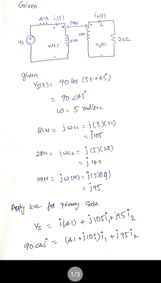
 Problem 1: The secondary winding of a transformer has a terminal voltage of v, (t) 282.8 sin 377t V. The turns ratio of the transformer is 100:200 (a0.50) The impedances of this transformer referred to the primary side are The equivalent circuit is shown below lf (a) If the secondary current of the transformer is i,()-7.07sin(3771-36.87) A, what is the primary current of this transformer? (20 points) HINTS: I. Peak values of the secondary voltage and current are specified in...
Problem 10.6-19 4 H 2 4 m 3 15 2 vy(t) 27 1 = v(t) 3...
 Problem 10.6-19 4 H 2 4 m 3 15 2 vy(t) 27 1 = v(t) 3 vit) $ 20 mF + v.(t) The input to this circuit the voltage source voltage is vs(t) = 8 cos(2 t) V. First, represent the circuit in the frequency domain using phasors and impedances. next, Apply KCL at nodes 2 and 4 and arrange the results in matrix form to to obtain the node equations: Tatjo 0 T 13-1-ja VO [, 1-ja][M]-[:) Determine the...
V2 = 8 (V) Ry = 8 (0) V2 = 26 (V) Problem 1 Using Kirchhoff's...
 V2 = 8 (V) Ry = 8 (0) V2 = 26 (V) Problem 1 Using Kirchhoff's rules in the circuit of image, A- Calculate the current in the circuit. B- Show the direction current in the circuit. C- Calculate the voltage across resistor R1 D- Calculate the power delivered to R2 E- After 15 minutes of working of circuit, how much energy is delivered to resistor Rı? T-28 V2 = 28 (V) V3 = 20 (7) R2 = 7(0)
Text problem 2.4: A single-phase source supplies a load of R 25 2 and a reactance...
 Text problem 2.4: A single-phase source supplies a load of R 25 2 and a reactance of Xc - are commected in paralel. The " 15 2, both of which are connected in parallel. The voltage across the combination is v(t) - v2(120) cos(wt -45°) v. a) Find V, the total current I, instantaneous current i(t), and the complex power. b) Repeat a) if instead of the capacitive reactance we had inductive reactance of XL = 20 Ω (Partial answer:...
Example 10.5-3 (See Example 10.5-3 in the textbook for the solution to a similar problem.) 2...
 Example 10.5-3 (See Example 10.5-3 in the textbook for the solution to a similar problem.) 2 mF 13o This circuit is at steady state. The input to this circuit is the voltage source voltage, vs(t), given by Vs(t) = 45cos(20t + (-50° ) | V The output voltage, Vo(t), can be expressed as Vo (t) = A cos(20t+ θ) v where A and θ are constants such that A > 0 and-180° < θ < 180°. Determine the values of...
Example 10.5-1 (See Example 10.5-1 in the textbook for the solution to a similar problem.) 68Ω...
 Example 10.5-1 (See Example 10.5-1 in the textbook for the solution to a similar problem.) 68Ω i(t) yso) 6.0H This circuit is at steady state. The input to this circuit is the voltage source voltage, vs(t), given by Vs(t) = 22cos(12t + (35° ) v The steady-state mesh current, (t), can be expressed as i(t)-A cos(12t + θ) mA 1809. Determine the values of the constants A and θ: where A and θ are constants such that A > 0...
problem 7 Problem-4 [10 Points] Find the Laplace transforms of the functions in Figure. 2 Figure....
 problem 7
Problem-4 [10 Points] Find the Laplace transforms of the functions in Figure. 2 Figure. 2: Triangular Function Problem-5 [10 Pointsl A system has the transfer function h(s) = (s1)(s +2) a) Find the impulse response of the system b) Determine the output y(t), given that the input is x(t) u(t) Problem-6 [10 Pointsl Use the Laplace transform to solve the differential equation +22+10v(t) 3 cos(2t) dt2 dt subject to v(0)-1, dv(O) Problem-7 [10 Points] Solve the integrodifferential equation...
problem 7
Problem-4 [10 Points] Find the Laplace transforms of the functions in Figure. 2 Figure. 2: Triangular Function Problem-5 [10 Pointsl A system has the transfer function h(s) = (s1)(s +2) a) Find the impulse response of the system b) Determine the output y(t), given that the input is x(t) u(t) Problem-6 [10 Pointsl Use the Laplace transform to solve the differential equation +22+10v(t) 3 cos(2t) dt2 dt subject to v(0)-1, dv(O) Problem-7 [10 Points] Solve the integrodifferential equation...
0 0 1 2 3 4 pts 5 10 15 20 pts Problem 6 In the...
 0 0 1 2 3 4 pts 5 10 15 20 pts Problem 6 In the Widlar current source shown here, there is a parasitic resistance Rx. Assume that the transistors have the same characteristics, are both in forward active mode, and both have finite Early voltage. Vt and Vºare DC power supply voltages vt ago. 1. FREE of Determine the analytical expression of the output resistance of this circuit. Je
 i PRINTER VERSION BACK NEXT Problem 11.9-19 (Companion Problem 2) 43 (0) 21H 20 w ASSIGNMENT RESOURCES HW.6 Problem 11.9-3 Problem 11.9-18 (Companion Problem 1). Problem 11.9-18 (Companion Problem 2) Problem 11.9-19 (Companion Problem 1). Problem 11.9-19 (Companion Problem 2) vio) 324H 30 HB v2(1) 3642 Primary Secondary The input to this circuit is the voltage source voltage Vs(t) = 92cos (8t+45) v Review Score Review Results by Study Objective Determine the complex power supplied by the voltage source: s....
 Problem 13.2-4 erial.11 oblem 13.2-3 roblem 13.2-4 oblem 13.2-4 Companion Problem) xample 16.7-1 9222 32 3 v.(0) 0.4H 3 ew Score ew Results by Study ective Site volt) The input to this circuit is the voltage-source voltage, vs(t). The output is the voltage, vo(t), across the series inductor and 32-S2 resistor. The network function of this circuit is H(W) * Determine the values of the constants k, z and p. k= V/V, z = 0 rad/s and p = c...
 Problem 1: The secondary winding of a transformer has a terminal voltage of v, (t) 282.8 sin 377t V. The turns ratio of the transformer is 100:200 (a0.50) The impedances of this transformer referred to the primary side are The equivalent circuit is shown below lf (a) If the secondary current of the transformer is i,()-7.07sin(3771-36.87) A, what is the primary current of this transformer? (20 points) HINTS: I. Peak values of the secondary voltage and current are specified in...
 Problem 10.6-19 4 H 2 4 m 3 15 2 vy(t) 27 1 = v(t) 3 vit) $ 20 mF + v.(t) The input to this circuit the voltage source voltage is vs(t) = 8 cos(2 t) V. First, represent the circuit in the frequency domain using phasors and impedances. next, Apply KCL at nodes 2 and 4 and arrange the results in matrix form to to obtain the node equations: Tatjo 0 T 13-1-ja VO [, 1-ja][M]-[:) Determine the...
 V2 = 8 (V) Ry = 8 (0) V2 = 26 (V) Problem 1 Using Kirchhoff's rules in the circuit of image, A- Calculate the current in the circuit. B- Show the direction current in the circuit. C- Calculate the voltage across resistor R1 D- Calculate the power delivered to R2 E- After 15 minutes of working of circuit, how much energy is delivered to resistor Rı? T-28 V2 = 28 (V) V3 = 20 (7) R2 = 7(0)
 Text problem 2.4: A single-phase source supplies a load of R 25 2 and a reactance of Xc - are commected in paralel. The " 15 2, both of which are connected in parallel. The voltage across the combination is v(t) - v2(120) cos(wt -45°) v. a) Find V, the total current I, instantaneous current i(t), and the complex power. b) Repeat a) if instead of the capacitive reactance we had inductive reactance of XL = 20 Ω (Partial answer:...
 Example 10.5-3 (See Example 10.5-3 in the textbook for the solution to a similar problem.) 2 mF 13o This circuit is at steady state. The input to this circuit is the voltage source voltage, vs(t), given by Vs(t) = 45cos(20t + (-50° ) | V The output voltage, Vo(t), can be expressed as Vo (t) = A cos(20t+ θ) v where A and θ are constants such that A > 0 and-180° < θ < 180°. Determine the values of...
 Example 10.5-1 (See Example 10.5-1 in the textbook for the solution to a similar problem.) 68Ω i(t) yso) 6.0H This circuit is at steady state. The input to this circuit is the voltage source voltage, vs(t), given by Vs(t) = 22cos(12t + (35° ) v The steady-state mesh current, (t), can be expressed as i(t)-A cos(12t + θ) mA 1809. Determine the values of the constants A and θ: where A and θ are constants such that A > 0...
 problem 7
Problem-4 [10 Points] Find the Laplace transforms of the functions in Figure. 2 Figure. 2: Triangular Function Problem-5 [10 Pointsl A system has the transfer function h(s) = (s1)(s +2) a) Find the impulse response of the system b) Determine the output y(t), given that the input is x(t) u(t) Problem-6 [10 Pointsl Use the Laplace transform to solve the differential equation +22+10v(t) 3 cos(2t) dt2 dt subject to v(0)-1, dv(O) Problem-7 [10 Points] Solve the integrodifferential equation...
problem 7
Problem-4 [10 Points] Find the Laplace transforms of the functions in Figure. 2 Figure. 2: Triangular Function Problem-5 [10 Pointsl A system has the transfer function h(s) = (s1)(s +2) a) Find the impulse response of the system b) Determine the output y(t), given that the input is x(t) u(t) Problem-6 [10 Pointsl Use the Laplace transform to solve the differential equation +22+10v(t) 3 cos(2t) dt2 dt subject to v(0)-1, dv(O) Problem-7 [10 Points] Solve the integrodifferential equation...
 0 0 1 2 3 4 pts 5 10 15 20 pts Problem 6 In the Widlar current source shown here, there is a parasitic resistance Rx. Assume that the transistors have the same characteristics, are both in forward active mode, and both have finite Early voltage. Vt and Vºare DC power supply voltages vt ago. 1. FREE of Determine the analytical expression of the output resistance of this circuit. Je
Most questions answered within 3 hours.
-
Where is the error in this code sequence?
String s1 = "Hello";
String s2 = "ello";...
asked 10 months ago -
Financial data for Joel de Paris, Inc., for last year
follow:
Joel de Paris, Inc.
Balance...
asked 10 months ago -
Consider this reaction:
Al2(SO4)3 (aq)+ BaCl3
(aq) Al2Cl6 (aq)- +
3BaSO4(s) . What is the...
asked 10 months ago -
Suppose that Savneet is considering increasing her
recent random sample from 20 car rentals to 40...
asked 10 months ago -
Trucks arrive at an unloading terminal at an average rate of 120
per hour.
Trucks arrive...
asked 10 months ago -
Why are methanol and ethanol completely soluble in water while
octanol is not very little soluble....
asked 10 months ago -
A facilities manager at a university reads in a research report
that the mean amount of...
asked 10 months ago -
When the CuSO4 is rehydrated by adding water to the anhydrous
compound, is this an endothermic...
asked 10 months ago -
A ray of sunlight is passing from diamond into crown glass; the
angle of incidence is...
asked 10 months ago -
A block of mass 0.249 kg is placed on top of a light, vertical
spring of...
asked 10 months ago -
how do the kidneys compensate in the presences of acidosis
a) trigger hyperventilate
b) reserve acid...
asked 10 months ago -
Question 501 pts
The rental rate of capital to the firm increases. Which of the
following...
asked 10 months ago