
Homework Answers
Add Answer to:
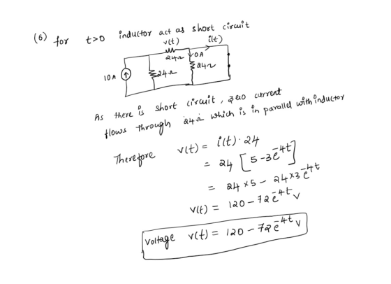
Problem 6) The inductor current in the circuit shown below is given by i(t)=5–3e * A...
The inductor current in the circuit shown in Figure is given by i(t)-5 + 11 e-4tA...
 The inductor current in the circuit shown in Figure is given by i(t)-5 + 11 e-4tA for t 2 0 Determine v(t) for t > O. 84 Ω 14H 84 Ω D10 A 84 Ω e-4t y for t20 2 Answer: v(t) -
Problem 1. For the circuit below, given a value foris 2.5Au(-t) solve for R1 so that...
 Problem 1. For the circuit below, given a value foris 2.5Au(-t) solve for R1 so that the initial capacitor voltage v(0) İs-10V Ri 20 mH 5Ω Problem 2. Circle one: The type of response for v() for t>0 would be classified as Over Damped Critically Damped Under Damped Problem 3. What is the form of the solution for v() for t>0 (form of solution Table 9.1)? Problem 4. What is the initial inductor current iL(0) in Amperes? iL(0)- Problem 5....
1) For the circuit below, a) Find i(t) fort > 0 b) Find vu(t) fort >...
 1) For the circuit below, a) Find i(t) fort > 0 b) Find vu(t) fort > 0 [you can do this by using your answer to part a) and the relationship between voltage across an inductor and current through an inductor] c) Plot your answers to parts a) and b) on separate plots. I lists to V. (4) 2H 2) For the circuit below, if the capacitor is fully discharged for t < 0, a) Find i(t) fort 0 you...
Problem 2: For the circuit shown below, find the following: The expression of i(t) fort >...
 Problem 2: For the circuit shown below, find the following: The expression of i(t) fort > 0. The voltage vc (t) fort > 0 Calculate the peak energy stored in the capacitor Calculate the real power dissipated in the load formed by R and C. b) d) 40 UF + 0 -V-24 Ve0 400 Hz
Problem 5: Consider the circuit shown in the figure below in which the initial inductor current...
 Problem 5: Consider the circuit shown in the figure below in which the initial inductor current and capacitor voltage are both zero. (a) Write the differential equation for vc(t). (b) Find the particular solution. (c) Is this circuit overdamped, critically damped, or underdamped? 4 0 i(t) vc()
Problem 8 In the given circuit i(0) = 3A Determine: a) i(t) (5 points) and b)...
 Problem 8 In the given circuit i(0) = 3A Determine: a) i(t) (5 points) and b) vo(t) (5 points) for t > 0 cos(5t) A 0 3h 5 *,
5. For the circuit shown below, find the current iu(t) flowing in the 4 H inductor...
 5. For the circuit shown below, find the current iu(t) flowing in the 4 H inductor fort20. 4Ω i, (t) t=0 4 H 12 V 50 mF 8Ω
Problem: The current in and the voltage across a 5 Hinductor are known to be zero...
 Problem:
The current in and the voltage across a 5 Hinductor are known to be zero fort <= 0. The voltage across the inductor is given by the graph in fort >= 0. A. Write the expressions that describe the current i(t) in piece-wise linear representation in suitable intervals. Find the current in the inductor at t2 s. B. Derive the expressions for the inductor power and energy. Use the passive sign convention. Sketch the current, power and energy waveform...
Problem:
The current in and the voltage across a 5 Hinductor are known to be zero fort <= 0. The voltage across the inductor is given by the graph in fort >= 0. A. Write the expressions that describe the current i(t) in piece-wise linear representation in suitable intervals. Find the current in the inductor at t2 s. B. Derive the expressions for the inductor power and energy. Use the passive sign convention. Sketch the current, power and energy waveform...
Problem 5(15 pts) The shown circuit is in DC steady state at t <0. The switch...
 Problem 5(15 pts) The shown circuit is in DC steady state at t <0. The switch moves from left to ri t-0. Find i(t) for t 20. 2t 10
Reinforcement Problem # 6 (20 pts.) A) Given The circuit shown is at equilibrium at t...
 Reinforcement Problem # 6 (20 pts.) A) Given The circuit shown is at equilibrium at t = 0 : 2.52 Ict) 00 2F 100 Vct) 2A B) Determine Step 1: The value of Vc(0), Step 2: The value of Vco). Step 3: The time constant , Step 4: The expression of voltage Vc(t) for t2 0 secs, Step 5: The expression of current Ic(t) fort 0 secs. Step 6: Show the MATLAB plot of Vo(t) and Ic(t) with your name....
 The inductor current in the circuit shown in Figure is given by i(t)-5 + 11 e-4tA for t 2 0 Determine v(t) for t > O. 84 Ω 14H 84 Ω D10 A 84 Ω e-4t y for t20 2 Answer: v(t) -
 Problem 1. For the circuit below, given a value foris 2.5Au(-t) solve for R1 so that the initial capacitor voltage v(0) İs-10V Ri 20 mH 5Ω Problem 2. Circle one: The type of response for v() for t>0 would be classified as Over Damped Critically Damped Under Damped Problem 3. What is the form of the solution for v() for t>0 (form of solution Table 9.1)? Problem 4. What is the initial inductor current iL(0) in Amperes? iL(0)- Problem 5....
 1) For the circuit below, a) Find i(t) fort > 0 b) Find vu(t) fort > 0 [you can do this by using your answer to part a) and the relationship between voltage across an inductor and current through an inductor] c) Plot your answers to parts a) and b) on separate plots. I lists to V. (4) 2H 2) For the circuit below, if the capacitor is fully discharged for t < 0, a) Find i(t) fort 0 you...
 Problem 2: For the circuit shown below, find the following: The expression of i(t) fort > 0. The voltage vc (t) fort > 0 Calculate the peak energy stored in the capacitor Calculate the real power dissipated in the load formed by R and C. b) d) 40 UF + 0 -V-24 Ve0 400 Hz
 Problem 5: Consider the circuit shown in the figure below in which the initial inductor current and capacitor voltage are both zero. (a) Write the differential equation for vc(t). (b) Find the particular solution. (c) Is this circuit overdamped, critically damped, or underdamped? 4 0 i(t) vc()
 Problem 8 In the given circuit i(0) = 3A Determine: a) i(t) (5 points) and b) vo(t) (5 points) for t > 0 cos(5t) A 0 3h 5 *,
 5. For the circuit shown below, find the current iu(t) flowing in the 4 H inductor fort20. 4Ω i, (t) t=0 4 H 12 V 50 mF 8Ω
 Problem:
The current in and the voltage across a 5 Hinductor are known to be zero fort <= 0. The voltage across the inductor is given by the graph in fort >= 0. A. Write the expressions that describe the current i(t) in piece-wise linear representation in suitable intervals. Find the current in the inductor at t2 s. B. Derive the expressions for the inductor power and energy. Use the passive sign convention. Sketch the current, power and energy waveform...
Problem:
The current in and the voltage across a 5 Hinductor are known to be zero fort <= 0. The voltage across the inductor is given by the graph in fort >= 0. A. Write the expressions that describe the current i(t) in piece-wise linear representation in suitable intervals. Find the current in the inductor at t2 s. B. Derive the expressions for the inductor power and energy. Use the passive sign convention. Sketch the current, power and energy waveform...
 Problem 5(15 pts) The shown circuit is in DC steady state at t <0. The switch moves from left to ri t-0. Find i(t) for t 20. 2t 10
 Reinforcement Problem # 6 (20 pts.) A) Given The circuit shown is at equilibrium at t = 0 : 2.52 Ict) 00 2F 100 Vct) 2A B) Determine Step 1: The value of Vc(0), Step 2: The value of Vco). Step 3: The time constant , Step 4: The expression of voltage Vc(t) for t2 0 secs, Step 5: The expression of current Ic(t) fort 0 secs. Step 6: Show the MATLAB plot of Vo(t) and Ic(t) with your name....
Most questions answered within 3 hours.
-
Where is the error in this code sequence?
String s1 = "Hello";
String s2 = "ello";...
asked 10 months ago -
Financial data for Joel de Paris, Inc., for last year
follow:
Joel de Paris, Inc.
Balance...
asked 10 months ago -
Consider this reaction:
Al2(SO4)3 (aq)+ BaCl3
(aq) Al2Cl6 (aq)- +
3BaSO4(s) . What is the...
asked 10 months ago -
Suppose that Savneet is considering increasing her
recent random sample from 20 car rentals to 40...
asked 10 months ago -
Trucks arrive at an unloading terminal at an average rate of 120
per hour.
Trucks arrive...
asked 10 months ago -
Why are methanol and ethanol completely soluble in water while
octanol is not very little soluble....
asked 10 months ago -
A facilities manager at a university reads in a research report
that the mean amount of...
asked 10 months ago -
When the CuSO4 is rehydrated by adding water to the anhydrous
compound, is this an endothermic...
asked 10 months ago -
A ray of sunlight is passing from diamond into crown glass; the
angle of incidence is...
asked 10 months ago -
A block of mass 0.249 kg is placed on top of a light, vertical
spring of...
asked 10 months ago -
how do the kidneys compensate in the presences of acidosis
a) trigger hyperventilate
b) reserve acid...
asked 10 months ago -
Question 501 pts
The rental rate of capital to the firm increases. Which of the
following...
asked 10 months ago