b) Flashing LEDs are to be designed for decoration. There is a total of 7 LEDs...
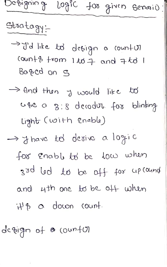
b) Flashing LEDs are to be designed for decoration. There is a total of 7 LEDs controlled by a switch. It works such that
1. When S=0, the LEDs are turned ON one after the other beginning from 1 to 7. When the LEDs flash in this manner the 3rd LED is skipped.
2. When S=1, the LEDs are turned ON one after the other but now beginning from 7 to 1.
When the LEDS flash in this manner the 4th LED is skipped.
For the above scenario do the following:
• Determine the State Table
• Draw the Circuit Diagram It must be described that which state represents what and a clear description of the state table and circuit diagram in words.
No credit will be given for solutions without explanations.
Homework Answers


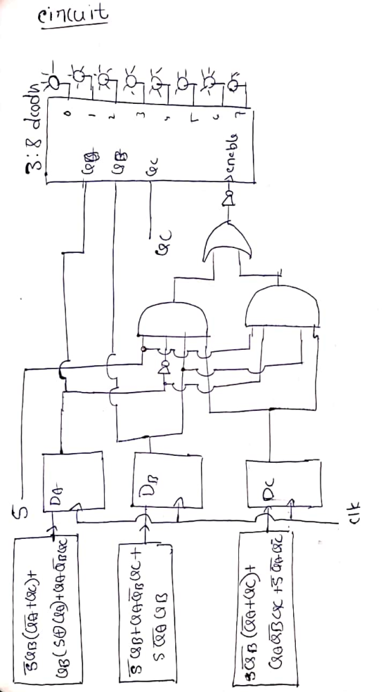

Here I have given state table and circuit diagram along with k-map solvation. Please notice that I have given the block diagrams instead of connecting them for the purpose of simplicity. When I connect them it might be clumsy.
If you have any queries please feel free to comment.
If you are satisfied with my work please UPVOTE.
Thank you.!
Add Answer to:
b) Flashing LEDs are to be designed for decoration. There is a
total of 7 LEDs...
A manual switch controlled 8-floor elevator is designed to operate such that when the master switch...
A manual switch controlled 8-floor elevator is designed to operate such that when the master switch S=0, it moves up (0,1,2. . . ) and when the switch S=1, it moves down (7,6,5. . . ). However, it has been observed that the elevator is experiencing the following problems: 1. When the S=1, the elevator instead of going down gets stuck on the current floor and does not move. (for example, if it is at the fourth floor, it remains...
You are to create a new application that will execute on your Arduino platform based upon...
 You are to create a new application that will execute on your Arduino platform based upon the Blink example that is available in the Arduino Examples folder that you downloaded as part of the IDE. Your application will use a toggle switch to interface with the user. The application will operate by controlling the LEDs based upon the position of the toggle switch. If the user moves the LEDs until new user input is provided. When the user moves the...
write in C language Decoration Lights Jojo is currently working in an office as a security....
 write in C language
Decoration Lights Jojo is currently working in an office as a security. Every night, after everyone returned home, he needs to make sure all decoration lights in the office is turned off. The decoration lights are unique: each of them has a timer that will switch the light on or off every two seconds. The lights are also arranged so well that each two neighboring lights will have different state (on/off). As long as the timer...
write in C language
Decoration Lights Jojo is currently working in an office as a security. Every night, after everyone returned home, he needs to make sure all decoration lights in the office is turned off. The decoration lights are unique: each of them has a timer that will switch the light on or off every two seconds. The lights are also arranged so well that each two neighboring lights will have different state (on/off). As long as the timer...
A sequential circuit is to be designed with two input lines A - "Pres> 800" and...
 A sequential circuit is to be designed with two input lines A - "Pres> 800" and B Temp> 100" and a single outputX-"ALARM". If a clock pulse arrives when AB 00 the circuit is to assume a reset state which may be labeled SO. Suppose the next "3" clock pulses following a resetting pulse coincide with thoe following sequence of input conditions 01- 11 - 01 The output"ALARM" is to be"1" coinciding with the third of such a string of...
Can someone please show me a circuit diagram so i can see how to construct this...
 Can someone please show me a circuit diagram so i can see how to
construct this on a bread board i am id 6 yhanks in advance
EEET-2251: Course & Projoct Guide 2018 EEET-2251: Cousc &Projoct Guide 2018 affic Light Controller A single switch must set your HC74 based state machine to the initial state (the U state This lab will get you to design a simple controller for a pedestrian crossing based on synchronous digital logic. You will master...
Can someone please show me a circuit diagram so i can see how to
construct this on a bread board i am id 6 yhanks in advance
EEET-2251: Course & Projoct Guide 2018 EEET-2251: Cousc &Projoct Guide 2018 affic Light Controller A single switch must set your HC74 based state machine to the initial state (the U state This lab will get you to design a simple controller for a pedestrian crossing based on synchronous digital logic. You will master...
7 (a)* The Planck constant h can be measured in an experiment using light-emitting diodes LEDs) Each LED used i...
 7 (a)* The Planck constant h can be measured in an experiment using light-emitting diodes LEDs) Each LED used in the experiment emits monochromatic light. Te wavelength λ of the emitted photons is detemined during the manufacturing process and is provided by the manufacturer When the p.d. across the LED reaches a specific minimum value suddenly switches on emitting photons of light of wavelength the LED andi are related by the energy equation eVi hh flying lead Fig. 7.1 LED...
A SEQUENCE DETECTOR that detects the sequence 00 must be designed whose present output z(k) is set to one when the past input u(k-1) is zero and the present input u(k) is also zero
 Question #2. Design of a Sequential Circuit: A SEQUENCE DETECTOR that detects the sequence 00 must be designed whose present output z(k) is set to one when the past input u(k-1) is zero and the present input u(k) is also zero, where for the other three possible combinations of the input pair u(k-1), u(k) the present output z(k) is set to zero. The state diagram for a sequential circuit that detects the input sequence 00 discussed above is given below:a) Complete...
ECE 260 HW 7 NAME 1. A sequential circuit has two JK flip-flops A and B,...
 ECE 260 HW 7 NAME 1. A sequential circuit has two JK flip-flops A and B, two inputs X and Y, and one output Z. The flip-flop input equations and circuit output equation are: (a) Draw the sequential circuit (b) Derive the state equations for Q and Q (c) Construct the state/output table (d) Draw the state diagram Note, for JK flip-flop: Q1O+KQ Design a sequential circuit with two JK flip-flops A and B and two inputs E and F....
answer a,b,c,d all of them one question 1 / 2 Question #2. Design of a Sequential...
 answer a,b,c,d all of them one question
1 / 2 Question #2. Design of a Sequential Circuit: A SEQUENCE DETECTOR that detects the sequence 11 must be designed whose present output z(k) is set to one when the past input (k-1) is one and the present input u(k) is also one, where for the other three possible combinations of the input pair u(k-1), uk) the present outputz(k) is set to zero. The state diagram for a sequential circuit that detects...
answer a,b,c,d all of them one question
1 / 2 Question #2. Design of a Sequential Circuit: A SEQUENCE DETECTOR that detects the sequence 11 must be designed whose present output z(k) is set to one when the past input (k-1) is one and the present input u(k) is also one, where for the other three possible combinations of the input pair u(k-1), uk) the present outputz(k) is set to zero. The state diagram for a sequential circuit that detects...
Used 2. (10 points) Design a sequential circuit, which has the potential of being combinational l...
 please answer the following?
used 2. (10 points) Design a sequential circuit, which has the potential of being combinational lock" if the number of inputs is expanded. The circuit has four inputs, labelet as reset, codeo, codel, and code2, and one output, labeled as match. Binary bits are coming to the four inputs sequentially, one bit at a time for each clock cycle. After reset - 1 for one clock cycle, the circuit searches for the first occurrence of the...
please answer the following?
used 2. (10 points) Design a sequential circuit, which has the potential of being combinational lock" if the number of inputs is expanded. The circuit has four inputs, labelet as reset, codeo, codel, and code2, and one output, labeled as match. Binary bits are coming to the four inputs sequentially, one bit at a time for each clock cycle. After reset - 1 for one clock cycle, the circuit searches for the first occurrence of the...
 You are to create a new application that will execute on your Arduino platform based upon the Blink example that is available in the Arduino Examples folder that you downloaded as part of the IDE. Your application will use a toggle switch to interface with the user. The application will operate by controlling the LEDs based upon the position of the toggle switch. If the user moves the LEDs until new user input is provided. When the user moves the...
 write in C language
Decoration Lights Jojo is currently working in an office as a security. Every night, after everyone returned home, he needs to make sure all decoration lights in the office is turned off. The decoration lights are unique: each of them has a timer that will switch the light on or off every two seconds. The lights are also arranged so well that each two neighboring lights will have different state (on/off). As long as the timer...
write in C language
Decoration Lights Jojo is currently working in an office as a security. Every night, after everyone returned home, he needs to make sure all decoration lights in the office is turned off. The decoration lights are unique: each of them has a timer that will switch the light on or off every two seconds. The lights are also arranged so well that each two neighboring lights will have different state (on/off). As long as the timer...
 A sequential circuit is to be designed with two input lines A - "Pres> 800" and B Temp> 100" and a single outputX-"ALARM". If a clock pulse arrives when AB 00 the circuit is to assume a reset state which may be labeled SO. Suppose the next "3" clock pulses following a resetting pulse coincide with thoe following sequence of input conditions 01- 11 - 01 The output"ALARM" is to be"1" coinciding with the third of such a string of...
 Can someone please show me a circuit diagram so i can see how to
construct this on a bread board i am id 6 yhanks in advance
EEET-2251: Course & Projoct Guide 2018 EEET-2251: Cousc &Projoct Guide 2018 affic Light Controller A single switch must set your HC74 based state machine to the initial state (the U state This lab will get you to design a simple controller for a pedestrian crossing based on synchronous digital logic. You will master...
Can someone please show me a circuit diagram so i can see how to
construct this on a bread board i am id 6 yhanks in advance
EEET-2251: Course & Projoct Guide 2018 EEET-2251: Cousc &Projoct Guide 2018 affic Light Controller A single switch must set your HC74 based state machine to the initial state (the U state This lab will get you to design a simple controller for a pedestrian crossing based on synchronous digital logic. You will master...
 7 (a)* The Planck constant h can be measured in an experiment using light-emitting diodes LEDs) Each LED used in the experiment emits monochromatic light. Te wavelength λ of the emitted photons is detemined during the manufacturing process and is provided by the manufacturer When the p.d. across the LED reaches a specific minimum value suddenly switches on emitting photons of light of wavelength the LED andi are related by the energy equation eVi hh flying lead Fig. 7.1 LED...
 ECE 260 HW 7 NAME 1. A sequential circuit has two JK flip-flops A and B, two inputs X and Y, and one output Z. The flip-flop input equations and circuit output equation are: (a) Draw the sequential circuit (b) Derive the state equations for Q and Q (c) Construct the state/output table (d) Draw the state diagram Note, for JK flip-flop: Q1O+KQ Design a sequential circuit with two JK flip-flops A and B and two inputs E and F....
 answer a,b,c,d all of them one question
1 / 2 Question #2. Design of a Sequential Circuit: A SEQUENCE DETECTOR that detects the sequence 11 must be designed whose present output z(k) is set to one when the past input (k-1) is one and the present input u(k) is also one, where for the other three possible combinations of the input pair u(k-1), uk) the present outputz(k) is set to zero. The state diagram for a sequential circuit that detects...
answer a,b,c,d all of them one question
1 / 2 Question #2. Design of a Sequential Circuit: A SEQUENCE DETECTOR that detects the sequence 11 must be designed whose present output z(k) is set to one when the past input (k-1) is one and the present input u(k) is also one, where for the other three possible combinations of the input pair u(k-1), uk) the present outputz(k) is set to zero. The state diagram for a sequential circuit that detects...
 please answer the following?
used 2. (10 points) Design a sequential circuit, which has the potential of being combinational lock" if the number of inputs is expanded. The circuit has four inputs, labelet as reset, codeo, codel, and code2, and one output, labeled as match. Binary bits are coming to the four inputs sequentially, one bit at a time for each clock cycle. After reset - 1 for one clock cycle, the circuit searches for the first occurrence of the...
please answer the following?
used 2. (10 points) Design a sequential circuit, which has the potential of being combinational lock" if the number of inputs is expanded. The circuit has four inputs, labelet as reset, codeo, codel, and code2, and one output, labeled as match. Binary bits are coming to the four inputs sequentially, one bit at a time for each clock cycle. After reset - 1 for one clock cycle, the circuit searches for the first occurrence of the...
Most questions answered within 3 hours.
-
Where is the error in this code sequence?
String s1 = "Hello";
String s2 = "ello";...
asked 11 months ago -
Financial data for Joel de Paris, Inc., for last year
follow:
Joel de Paris, Inc.
Balance...
asked 11 months ago -
Consider this reaction:
Al2(SO4)3 (aq)+ BaCl3
(aq) Al2Cl6 (aq)- +
3BaSO4(s) . What is the...
asked 11 months ago -
Suppose that Savneet is considering increasing her
recent random sample from 20 car rentals to 40...
asked 11 months ago -
Trucks arrive at an unloading terminal at an average rate of 120
per hour.
Trucks arrive...
asked 11 months ago -
Why are methanol and ethanol completely soluble in water while
octanol is not very little soluble....
asked 11 months ago -
A facilities manager at a university reads in a research report
that the mean amount of...
asked 11 months ago -
When the CuSO4 is rehydrated by adding water to the anhydrous
compound, is this an endothermic...
asked 11 months ago -
A ray of sunlight is passing from diamond into crown glass; the
angle of incidence is...
asked 11 months ago -
A block of mass 0.249 kg is placed on top of a light, vertical
spring of...
asked 11 months ago -
how do the kidneys compensate in the presences of acidosis
a) trigger hyperventilate
b) reserve acid...
asked 11 months ago -
Question 501 pts
The rental rate of capital to the firm increases. Which of the
following...
asked 11 months ago