
Homework Answers

Please forgive me for any calculation mistake and do comment for any short of queries.
Add Answer to:
The following is the torque versus angle of twist diagram for a 0.75 inch diameter steel...
The following is the torque versus angle of twist diagram for a 0.75 inch diameter steel...
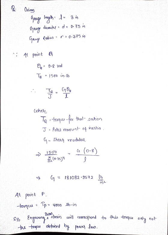
 The following is the torque versus angle of twist diagram for a 0.75 inch diameter steel bar tested in torsion. The gage length of the bar is 3 inches. The angle of rotation and torque at points Q and P are (0.8 radian, 1500 in-lb) and (11.3 radian, 4000 in-lb) respectively. The power-law curve fitting relation for the data above the yield point is given by T = 329880.21, where T is in in-lb and e is in radian. Torque...
The following is the torque versus angle of twist diagram for a 0.75 inch diameter steel...
 The following is the torque versus angle of twist diagram for a 0.75 inch diameter steel bar tested in torsion. The gage length of the bar is 3 inches. The angle of rotation and torque at points Q and P are (0.8 radian, 1500 in-lb) and (11.3 radian, 4000 in-lb) respectively. The power-law curve fitting relation for the data above the yield point is given by T = 329880.21, where T is in in-lb and g is in radian. Torque...
The following is the torque versus angle of twist diagram for a 0.75 inch diameter steel...
 The following is the torque versus angle of twist diagram for a 0.75 inch diameter steel bar tested in torsion. The gage length of the bar is 3 inches. The angle of rotation and torque at points Q and P are (0.8 radian, 1500 in-lb) and (11.3 radian, 4000 in-lb) respectively. The power-law curve fitting relation for the data above the yield point is given by T = 329880.21, where T is in in-lb and e is in radian. Torque...
Question 19 1 points Save Answer The following is the torque versus angle of twist diagram...
 Question 19 1 points Save Answer The following is the torque versus angle of twist diagram for a 0.75 inch diameter steel bar tested in torsion. The gage length of the bar is 3 inches. The angle of rotation and torque at points Q and Pare (0.8 radian, 1500 in-Ib) and (11.3 radian, 4000 in-Ib) respectively. The power-law curve fitting relation for the data above the yield point is given by T=329880.21, where T is in in-Ib and 2 is...
Question 20 1 points Saved The following is the torque versus angle of twist diagram for...
 Question 20 1 points Saved The following is the torque versus angle of twist diagram for a 0.75 inch diameter steel bar tested in torsion. The gage length of the bar is 3 inches. The angle of rotation and torque at points and Pare (0.8 radian, 1500 in-Ib) and (11.3 radian, 4000 in-lb) respectively. The power-law curve fitting relation for the data above the yield point is given by T-329800.21, where is in in-Ib and is in radian. Torque T...
Saved Question 20 1 points The following is the torque versus angle of twist diagram for...
 Saved Question 20 1 points The following is the torque versus angle of twist diagram for a 0.75 inch diameter steel bar tested in torsion. The gage length of the bar is 3 inches. The angle of rotation and torque at points and Pare (0.8 radian, 1500 in-lb) and (11.3 radian, 4000 in-Ib) respectively. The power-law curve fitting relation for the data above the yield point is given by T-32980021, where T is in in-lb and is in radian Torque...
Aluminum Steel 22 Kip.ft 20 Kip.ft Question A 4 inch diameter composite shaft is subjected to...
 Aluminum Steel 22 Kip.ft 20 Kip.ft Question A 4 inch diameter composite shaft is subjected to the torques as shown. The section are perfectly bonded rigidly together. Use Gsteel = 11,600 ksi and Galuminum = 4000 ksi. Determine the maximum shearing stress in the shaft and the magnitude of the angle of twist of point D with respect to point A. 7.4 Kip.ft T - - 4.9ft 6.6 ft 3.3ft TP Shear Stress: t = Angle of Twist: Ø= Polar...
igwe 3 3, (4%) For a prismatic bar in the Figure 3, under a torque T...
 igwe 3 3, (4%) For a prismatic bar in the Figure 3, under a torque T (Nm) which twists the bar, with length L (m) and radius r (m), for a small angle ? (radian): (Hint 3.1. The maximum shear stress (Tmax) is 3.2. The shear strain at the surface (Ymax) is (a) rmax degree (b) Ymax radian (c) Year-! deg/m (d) Ym", (no uni) 3.3. The shear modulus of elasticity G can be determined from known angle of twist...
 The following is the torque versus angle of twist diagram for a 0.75 inch diameter steel bar tested in torsion. The gage length of the bar is 3 inches. The angle of rotation and torque at points Q and P are (0.8 radian, 1500 in-lb) and (11.3 radian, 4000 in-lb) respectively. The power-law curve fitting relation for the data above the yield point is given by T = 329880.21, where T is in in-lb and e is in radian. Torque...
 The following is the torque versus angle of twist diagram for a 0.75 inch diameter steel bar tested in torsion. The gage length of the bar is 3 inches. The angle of rotation and torque at points Q and P are (0.8 radian, 1500 in-lb) and (11.3 radian, 4000 in-lb) respectively. The power-law curve fitting relation for the data above the yield point is given by T = 329880.21, where T is in in-lb and g is in radian. Torque...
 The following is the torque versus angle of twist diagram for a 0.75 inch diameter steel bar tested in torsion. The gage length of the bar is 3 inches. The angle of rotation and torque at points Q and P are (0.8 radian, 1500 in-lb) and (11.3 radian, 4000 in-lb) respectively. The power-law curve fitting relation for the data above the yield point is given by T = 329880.21, where T is in in-lb and g is in radian. Torque...
 The following is the torque versus angle of twist diagram for a 0.75 inch diameter steel bar tested in torsion. The gage length of the bar is 3 inches. The angle of rotation and torque at points Q and P are (0.8 radian, 1500 in-lb) and (11.3 radian, 4000 in-lb) respectively. The power-law curve fitting relation for the data above the yield point is given by T = 329880.21, where T is in in-lb and g is in radian. Torque...
 The following is the torque versus angle of twist diagram for a 0.75 inch diameter steel bar tested in torsion. The gage length of the bar is 3 inches. The angle of rotation and torque at points Q and P are (0.8 radian, 1500 in-lb) and (11.3 radian, 4000 in-lb) respectively. The power-law curve fitting relation for the data above the yield point is given by T = 329880.21, where T is in in-lb and e is in radian. Torque...
 Question 19 1 points Save Answer The following is the torque versus angle of twist diagram for a 0.75 inch diameter steel bar tested in torsion. The gage length of the bar is 3 inches. The angle of rotation and torque at points Q and Pare (0.8 radian, 1500 in-Ib) and (11.3 radian, 4000 in-Ib) respectively. The power-law curve fitting relation for the data above the yield point is given by T=329880.21, where T is in in-Ib and 2 is...
 Question 20 1 points Saved The following is the torque versus angle of twist diagram for a 0.75 inch diameter steel bar tested in torsion. The gage length of the bar is 3 inches. The angle of rotation and torque at points and Pare (0.8 radian, 1500 in-Ib) and (11.3 radian, 4000 in-lb) respectively. The power-law curve fitting relation for the data above the yield point is given by T-329800.21, where is in in-Ib and is in radian. Torque T...
 Saved Question 20 1 points The following is the torque versus angle of twist diagram for a 0.75 inch diameter steel bar tested in torsion. The gage length of the bar is 3 inches. The angle of rotation and torque at points and Pare (0.8 radian, 1500 in-lb) and (11.3 radian, 4000 in-Ib) respectively. The power-law curve fitting relation for the data above the yield point is given by T-32980021, where T is in in-lb and is in radian Torque...
 Aluminum Steel 22 Kip.ft 20 Kip.ft Question A 4 inch diameter composite shaft is subjected to the torques as shown. The section are perfectly bonded rigidly together. Use Gsteel = 11,600 ksi and Galuminum = 4000 ksi. Determine the maximum shearing stress in the shaft and the magnitude of the angle of twist of point D with respect to point A. 7.4 Kip.ft T - - 4.9ft 6.6 ft 3.3ft TP Shear Stress: t = Angle of Twist: Ø= Polar...
 igwe 3 3, (4%) For a prismatic bar in the Figure 3, under a torque T (Nm) which twists the bar, with length L (m) and radius r (m), for a small angle ? (radian): (Hint 3.1. The maximum shear stress (Tmax) is 3.2. The shear strain at the surface (Ymax) is (a) rmax degree (b) Ymax radian (c) Year-! deg/m (d) Ym", (no uni) 3.3. The shear modulus of elasticity G can be determined from known angle of twist...
Most questions answered within 3 hours.
-
Where is the error in this code sequence?
String s1 = "Hello";
String s2 = "ello";...
asked 11 months ago -
Financial data for Joel de Paris, Inc., for last year
follow:
Joel de Paris, Inc.
Balance...
asked 11 months ago -
Consider this reaction:
Al2(SO4)3 (aq)+ BaCl3
(aq) Al2Cl6 (aq)- +
3BaSO4(s) . What is the...
asked 11 months ago -
Suppose that Savneet is considering increasing her
recent random sample from 20 car rentals to 40...
asked 11 months ago -
Trucks arrive at an unloading terminal at an average rate of 120
per hour.
Trucks arrive...
asked 11 months ago -
Why are methanol and ethanol completely soluble in water while
octanol is not very little soluble....
asked 11 months ago -
A facilities manager at a university reads in a research report
that the mean amount of...
asked 11 months ago -
When the CuSO4 is rehydrated by adding water to the anhydrous
compound, is this an endothermic...
asked 11 months ago -
A ray of sunlight is passing from diamond into crown glass; the
angle of incidence is...
asked 11 months ago -
A block of mass 0.249 kg is placed on top of a light, vertical
spring of...
asked 11 months ago -
how do the kidneys compensate in the presences of acidosis
a) trigger hyperventilate
b) reserve acid...
asked 11 months ago -
Question 501 pts
The rental rate of capital to the firm increases. Which of the
following...
asked 11 months ago