
Homework Answers
Matlab script to plot root locus
n=[1 -4 20];
d=[1 6 8];
h=tf(n,d); % calculates the transfer function
rlocus(h) % plots the root locus
rootlocus matlab plot
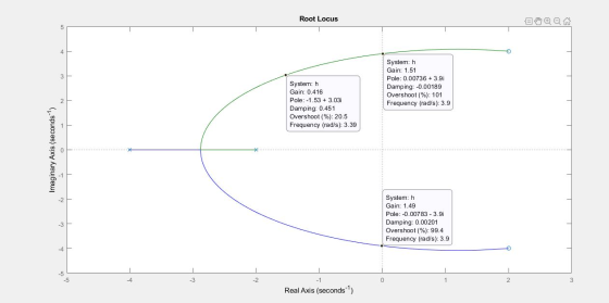
from this root locus plot
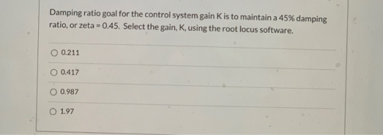
question 1
the damping ratio is 0.45 when gain is 0.417
so answer is option 2
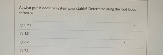
question 2
the system becomes unstable when plot(poles) moves to right side of jw axis
this happes at k =1.5
so answer is option2
Add Answer to:
Matlab
needs to be done by matlab
Create a root locus plot to determine design a...
% MATLAB allows root loci to be plotted with the % rlocus(GH) command, where G(s)H(s) =...
 % MATLAB allows root loci to be plotted with the
% rlocus(GH) command, where G(s)H(s) = numgh/dengh and GH is an
LTI transfer-
% function object. Points on the root locus can be selected
interactively
% using [K,p] = rlocfind(GH) command. MATLAB yields gain(K)
at
% that point as well as all other poles(p) that have that gain.
We can zoom
% in and out of root locus by changing range of axis values
using
% command axis([xmin,xmax,ymin,ymax]). root locus...
% MATLAB allows root loci to be plotted with the
% rlocus(GH) command, where G(s)H(s) = numgh/dengh and GH is an
LTI transfer-
% function object. Points on the root locus can be selected
interactively
% using [K,p] = rlocfind(GH) command. MATLAB yields gain(K)
at
% that point as well as all other poles(p) that have that gain.
We can zoom
% in and out of root locus by changing range of axis values
using
% command axis([xmin,xmax,ymin,ymax]). root locus...
1- [a] For positive values of K, plot the root locus for a unity negative feedback...
 1- [a] For positive values of K, plot the root locus for a unity negative feedback control system having the following open-loop transfer function: K G(s)= (5 + 1)(8 + 4)(8 + 7) For what values of gain K does the system become unstable? Find also the value of k at which the damping ratio is 0.5 and the closed loop poles. (25%) [b] The characteristic equations of linear control systems are given below. Apply Routh-Hurwitz criterion to determine the...
Q1. Show analytically that the Root Locus for the unity feedback system with open loop transfer f...
 Q1. Show analytically that the Root Locus for the unity feedback system with open loop transfer function: (a) [10 marks] K(s 4) (s + 2) is a circle, and find the centre and the radius. Determine the minimum value of the damping ratio and the corresponding value of K (b) The root locus of the open loop transfer function: [10 marks] s(s26s +15) is depicted in Figure Q1(b). Find the minimum value of gain K that will render the system...
[7] Sketch the root locus for the unity feedback system whose open loop transfer function is K G(s) Draw the root locus...
 [7] Sketch the root locus for the unity feedback system whose open loop transfer function is K G(s) Draw the root locus of the system with the gain K as a variable s(s+4) (s2+4s+20)' Determine asymptotes, centroid,, breakaway point, angle of departure, and the gain at which root locus crosses jw -axis.
[7] Sketch the root locus for the unity feedback system whose open loop transfer function is K G(s) Draw the root locus of the system with the gain...
[7] Sketch the root locus for the unity feedback system whose open loop transfer function is K G(s) Draw the root locus of the system with the gain K as a variable s(s+4) (s2+4s+20)' Determine asymptotes, centroid,, breakaway point, angle of departure, and the gain at which root locus crosses jw -axis.
[7] Sketch the root locus for the unity feedback system whose open loop transfer function is K G(s) Draw the root locus of the system with the gain...
Sketch the root locus plot of a unity feedback system with an open loop transfer function...
Sketch the root locus plot of a unity feedback system with an open loop transfer function G(s) = K / s (s+2) (s+4) Determine the value of K so that the dominant pair of complex poles of the system has a damping ratio of 0.5.
% We can couple the design of gain on the root locus with a % step-response...
 % We can couple the design of gain on the root locus with a
% step-response simulation for the gain selected. We introduce
the command
% rlocus(G,K), which allows us to specify the range of gain, K,
for plotting the root
% locus. This command will help us smooth the usual root locus
plot by equivalently
% specifying more points via the argument, K. Notice that the
first root locus
% plotted without the argument K is not smooth. We...
% We can couple the design of gain on the root locus with a
% step-response simulation for the gain selected. We introduce
the command
% rlocus(G,K), which allows us to specify the range of gain, K,
for plotting the root
% locus. This command will help us smooth the usual root locus
plot by equivalently
% specifying more points via the argument, K. Notice that the
first root locus
% plotted without the argument K is not smooth. We...
If the initial cone A E Re has a root locus plot started in Figure P1. Determine the following about the root locus...
 If the initial cone A E Re has a root locus plot started in Figure P1. Determine the following about the root locus determine a) the transfer f a) Of points A, B & C indicated on the real axis which are on the root locus? Ans b) the DC gain of b) How many zeros are there at infinity? Ans c) What angles do the infinity zero asymptote(s) make with the positive real axis? Ans d) Where do the...
Please be specific about the root locus and Matlab code. Problem 2 For the feedback system...
 Please be specific about the root locus and Matlab code.
Problem 2 For the feedback system shown in the diagram below, use the root locus design method to find the value of the gain K that results in dominant closed-loop poles with a damping ratio Ç-0.5- Verify your solution with Matlab, and attach the plotted solution.
Please be specific about the root locus and Matlab code.
Problem 2 For the feedback system shown in the diagram below, use the root locus design method to find the value of the gain K that results in dominant closed-loop poles with a damping ratio Ç-0.5- Verify your solution with Matlab, and attach the plotted solution.
A robot force control system with unity feedback has a loop transfer function [6 7.11 Tood transf...
 A robot force control system with unity feedback has a loop transfer function [6 7.11 Tood transfer function (6l K(s +2.5) (s2 + 2s 2) (s2 + 4s + 5) (a) Find the gain K that results in dominant roots with a damping ratio of 0.707. Sketch the root locus. (b) Find the actual percent overshoot and peak time for the gain K of part (a)
A robot force control system with unity feedback has a loop transfer function [6...
A robot force control system with unity feedback has a loop transfer function [6 7.11 Tood transfer function (6l K(s +2.5) (s2 + 2s 2) (s2 + 4s + 5) (a) Find the gain K that results in dominant roots with a damping ratio of 0.707. Sketch the root locus. (b) Find the actual percent overshoot and peak time for the gain K of part (a)
A robot force control system with unity feedback has a loop transfer function [6...
7. Use MATLAB root locus to analyze the system on the right. Marks 10 Show that...
 7. Use MATLAB root locus to analyze the system on the right. Marks 10 Show that the system is unstable for all values of K. Add a zero at s =-1, and show that this stabilizes the system. With the additional zero, determine the value of K such that the dominate pair of complex poles of the system has a damping ration of 0.5. Use Simulink to determine the step function of the uncompensated system. Use Simulink to determine the...
 % MATLAB allows root loci to be plotted with the
% rlocus(GH) command, where G(s)H(s) = numgh/dengh and GH is an
LTI transfer-
% function object. Points on the root locus can be selected
interactively
% using [K,p] = rlocfind(GH) command. MATLAB yields gain(K)
at
% that point as well as all other poles(p) that have that gain.
We can zoom
% in and out of root locus by changing range of axis values
using
% command axis([xmin,xmax,ymin,ymax]). root locus...
% MATLAB allows root loci to be plotted with the
% rlocus(GH) command, where G(s)H(s) = numgh/dengh and GH is an
LTI transfer-
% function object. Points on the root locus can be selected
interactively
% using [K,p] = rlocfind(GH) command. MATLAB yields gain(K)
at
% that point as well as all other poles(p) that have that gain.
We can zoom
% in and out of root locus by changing range of axis values
using
% command axis([xmin,xmax,ymin,ymax]). root locus...
 1- [a] For positive values of K, plot the root locus for a unity negative feedback control system having the following open-loop transfer function: K G(s)= (5 + 1)(8 + 4)(8 + 7) For what values of gain K does the system become unstable? Find also the value of k at which the damping ratio is 0.5 and the closed loop poles. (25%) [b] The characteristic equations of linear control systems are given below. Apply Routh-Hurwitz criterion to determine the...
 Q1. Show analytically that the Root Locus for the unity feedback system with open loop transfer function: (a) [10 marks] K(s 4) (s + 2) is a circle, and find the centre and the radius. Determine the minimum value of the damping ratio and the corresponding value of K (b) The root locus of the open loop transfer function: [10 marks] s(s26s +15) is depicted in Figure Q1(b). Find the minimum value of gain K that will render the system...
 [7] Sketch the root locus for the unity feedback system whose open loop transfer function is K G(s) Draw the root locus of the system with the gain K as a variable s(s+4) (s2+4s+20)' Determine asymptotes, centroid,, breakaway point, angle of departure, and the gain at which root locus crosses jw -axis.
[7] Sketch the root locus for the unity feedback system whose open loop transfer function is K G(s) Draw the root locus of the system with the gain...
[7] Sketch the root locus for the unity feedback system whose open loop transfer function is K G(s) Draw the root locus of the system with the gain K as a variable s(s+4) (s2+4s+20)' Determine asymptotes, centroid,, breakaway point, angle of departure, and the gain at which root locus crosses jw -axis.
[7] Sketch the root locus for the unity feedback system whose open loop transfer function is K G(s) Draw the root locus of the system with the gain...
 % We can couple the design of gain on the root locus with a
% step-response simulation for the gain selected. We introduce
the command
% rlocus(G,K), which allows us to specify the range of gain, K,
for plotting the root
% locus. This command will help us smooth the usual root locus
plot by equivalently
% specifying more points via the argument, K. Notice that the
first root locus
% plotted without the argument K is not smooth. We...
% We can couple the design of gain on the root locus with a
% step-response simulation for the gain selected. We introduce
the command
% rlocus(G,K), which allows us to specify the range of gain, K,
for plotting the root
% locus. This command will help us smooth the usual root locus
plot by equivalently
% specifying more points via the argument, K. Notice that the
first root locus
% plotted without the argument K is not smooth. We...
 If the initial cone A E Re has a root locus plot started in Figure P1. Determine the following about the root locus determine a) the transfer f a) Of points A, B & C indicated on the real axis which are on the root locus? Ans b) the DC gain of b) How many zeros are there at infinity? Ans c) What angles do the infinity zero asymptote(s) make with the positive real axis? Ans d) Where do the...
 Please be specific about the root locus and Matlab code.
Problem 2 For the feedback system shown in the diagram below, use the root locus design method to find the value of the gain K that results in dominant closed-loop poles with a damping ratio Ç-0.5- Verify your solution with Matlab, and attach the plotted solution.
Please be specific about the root locus and Matlab code.
Problem 2 For the feedback system shown in the diagram below, use the root locus design method to find the value of the gain K that results in dominant closed-loop poles with a damping ratio Ç-0.5- Verify your solution with Matlab, and attach the plotted solution.
 A robot force control system with unity feedback has a loop transfer function [6 7.11 Tood transfer function (6l K(s +2.5) (s2 + 2s 2) (s2 + 4s + 5) (a) Find the gain K that results in dominant roots with a damping ratio of 0.707. Sketch the root locus. (b) Find the actual percent overshoot and peak time for the gain K of part (a)
A robot force control system with unity feedback has a loop transfer function [6...
A robot force control system with unity feedback has a loop transfer function [6 7.11 Tood transfer function (6l K(s +2.5) (s2 + 2s 2) (s2 + 4s + 5) (a) Find the gain K that results in dominant roots with a damping ratio of 0.707. Sketch the root locus. (b) Find the actual percent overshoot and peak time for the gain K of part (a)
A robot force control system with unity feedback has a loop transfer function [6...
 7. Use MATLAB root locus to analyze the system on the right. Marks 10 Show that the system is unstable for all values of K. Add a zero at s =-1, and show that this stabilizes the system. With the additional zero, determine the value of K such that the dominate pair of complex poles of the system has a damping ration of 0.5. Use Simulink to determine the step function of the uncompensated system. Use Simulink to determine the...
Most questions answered within 3 hours.
-
Where is the error in this code sequence?
String s1 = "Hello";
String s2 = "ello";...
asked 11 months ago -
Financial data for Joel de Paris, Inc., for last year
follow:
Joel de Paris, Inc.
Balance...
asked 11 months ago -
Consider this reaction:
Al2(SO4)3 (aq)+ BaCl3
(aq) Al2Cl6 (aq)- +
3BaSO4(s) . What is the...
asked 11 months ago -
Suppose that Savneet is considering increasing her
recent random sample from 20 car rentals to 40...
asked 11 months ago -
Trucks arrive at an unloading terminal at an average rate of 120
per hour.
Trucks arrive...
asked 11 months ago -
Why are methanol and ethanol completely soluble in water while
octanol is not very little soluble....
asked 11 months ago -
A facilities manager at a university reads in a research report
that the mean amount of...
asked 11 months ago -
When the CuSO4 is rehydrated by adding water to the anhydrous
compound, is this an endothermic...
asked 11 months ago -
A ray of sunlight is passing from diamond into crown glass; the
angle of incidence is...
asked 11 months ago -
A block of mass 0.249 kg is placed on top of a light, vertical
spring of...
asked 11 months ago -
how do the kidneys compensate in the presences of acidosis
a) trigger hyperventilate
b) reserve acid...
asked 11 months ago -
Question 501 pts
The rental rate of capital to the firm increases. Which of the
following...
asked 11 months ago