
Homework Answers
Add Answer to:
Question 7 Considering the figure shown, the shear strain at point A relative to the x-yaxes...
Question 7 Considering the figure shown, the shear strain at point A relative to the x-yaxes...
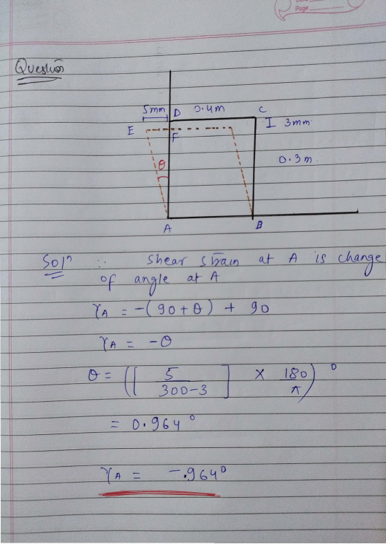
 Question 7 Considering the figure shown, the shear strain at point A relative to the x-yaxes is: 5 mm у 0.4 m 3 mm 0.3 m А 0.964 0 -0.964 0.0168 -0.0168 MacBook Air 80 GOS 000 F4 FS 97 # $ 4 A 3 % 5 & ON 7 8
Considering the figure shown, the shear strain at point A relative to the x-y axes is:...
 Considering the figure shown, the shear strain at point A relative to the x-y axes is: у -16 418/ B' CH B С 13 163 A D х 44
Considering the figure shown, the shear strain at point A relative to the x-y axes is:...
 Considering the figure shown, the shear strain at point A relative to the x-y axes is: 181 B' 1161 CH B с 13 163 A х 44 o 0.12 0 -0.12 O 0.1023 0 -0.1023
20 Question 14 Consider the simply supported beam shown in the figure below. Let x be...
 20 Question 14 Consider the simply supported beam shown in the figure below. Let x be the distance measured from left end of the beam. 1. Determine the vertical reactions at A and C 2. Write the equations for shear and moment for the section of the member between B and C. 3. Draw the shear and moment diagrams for the entire beam, specifying values at changes in loading and locations where the shear is o. 8 kN/m 48 KN...
Consider the simply supported beam shown in the figure below. Let x be the distance measured...
 Consider the simply supported beam shown in the figure below. Let x be the distance measured from left end of the beam. 1. Determine the vertical reactions at A and C 2. Write the equations for shear and moment for the section of the şember between B and C. 3. Draw the shear and moment diagrams for the entire beam, specifying values at changes in loading and locations where the shear is 0. 8 kN/m 48 KN 24 N- MacBook...
For a state of pure shear stress acting on a point shown in the figure, which...
 For a state of pure shear stress acting on a point shown in the figure, which of the following equations represents the corresponding transformation equation of a normal stress (0,"? (Note: use the equations of stress transformation and principal stresses) Y 5x Soy 0 Тух A) (1 + cos20) B) - sine C) Txy sin20 D) Txy cos20 ОА OB Ос OD MacBook Air 30 000 $ % og * 4 5
Consider the simply supported beam shown in the figure below. Let x be the distance measured...
 Consider the simply supported beam shown in the figure below. Let x be the distance measured from left end of the beam. 1. Determine the vertical reactions at A and C 2. Write the equations for shear and moment for the section of the member between B and c. 3. Draw the shear and moment diagrams for the entire beam, specifying values at changes in loading and locations where the shear is 0. 8 kN/m 48 KN 24 KN-m MacBook...
The square deforms into the position shown by the dashed lines. (Figure 1) The dimensions are...
 The square deforms into the position shown by the dashed lines. (Figure 1) The dimensions are S 49 mm, S,-54 mm, ΔΧ1-4 mm, and ΔΖ2 : 8 mm. Side D'B, remains horizontal Part A Determine the shear strain at A relative to the z, y axes. Express your answer to three significant figures and include appropriate units Tay262-102 rad Previous A nswe Figure 1 of 1 Correct Ar Part B Determine the shear strain at B relative to the z,...
If the material obeys a shear stress-strain relation (Figure 2) of T = 500 7/4 MPa,...
 If the material obeys a shear stress-strain relation (Figure 2) of T = 500 7/4 MPa, determine the torque that must be applied to the shaft so that the maximum shear strain becomes 0.005 rad. Express your answer to three significant figures and include appropriate units. ? C: Å T = 152000 o 2 N·m Submit Previous Answers Request Answer X Incorrect; Try Again; 26 attempts remaining T (MPa) 0.008. -Y (rad) a ) A torque is applied to the...
 Question 7 Considering the figure shown, the shear strain at point A relative to the x-yaxes is: 5 mm у 0.4 m 3 mm 0.3 m А 0.964 0 -0.964 0.0168 -0.0168 MacBook Air 80 GOS 000 F4 FS 97 # $ 4 A 3 % 5 & ON 7 8
 Considering the figure shown, the shear strain at point A relative to the x-y axes is: у -16 418/ B' CH B С 13 163 A D х 44
 Considering the figure shown, the shear strain at point A relative to the x-y axes is: 181 B' 1161 CH B с 13 163 A х 44 o 0.12 0 -0.12 O 0.1023 0 -0.1023
 20 Question 14 Consider the simply supported beam shown in the figure below. Let x be the distance measured from left end of the beam. 1. Determine the vertical reactions at A and C 2. Write the equations for shear and moment for the section of the member between B and C. 3. Draw the shear and moment diagrams for the entire beam, specifying values at changes in loading and locations where the shear is o. 8 kN/m 48 KN...
 Consider the simply supported beam shown in the figure below. Let x be the distance measured from left end of the beam. 1. Determine the vertical reactions at A and C 2. Write the equations for shear and moment for the section of the şember between B and C. 3. Draw the shear and moment diagrams for the entire beam, specifying values at changes in loading and locations where the shear is 0. 8 kN/m 48 KN 24 N- MacBook...
 For a state of pure shear stress acting on a point shown in the figure, which of the following equations represents the corresponding transformation equation of a normal stress (0,"? (Note: use the equations of stress transformation and principal stresses) Y 5x Soy 0 Тух A) (1 + cos20) B) - sine C) Txy sin20 D) Txy cos20 ОА OB Ос OD MacBook Air 30 000 $ % og * 4 5
 Consider the simply supported beam shown in the figure below. Let x be the distance measured from left end of the beam. 1. Determine the vertical reactions at A and C 2. Write the equations for shear and moment for the section of the member between B and c. 3. Draw the shear and moment diagrams for the entire beam, specifying values at changes in loading and locations where the shear is 0. 8 kN/m 48 KN 24 KN-m MacBook...
 Consider the simply supported beam shown in the figure below. Let x be the distance measured from left end of the beam. 1. Determine the vertical reactions at A and C 2. Write the equations for shear and moment for the section of the member between B and c. 3. Draw the shear and moment diagrams for the entire beam, specifying values at changes in loading and locations where the shear is 0. 8 kN/m 48 KN 24 KN-m MacBook...
 The square deforms into the position shown by the dashed lines. (Figure 1) The dimensions are S 49 mm, S,-54 mm, ΔΧ1-4 mm, and ΔΖ2 : 8 mm. Side D'B, remains horizontal Part A Determine the shear strain at A relative to the z, y axes. Express your answer to three significant figures and include appropriate units Tay262-102 rad Previous A nswe Figure 1 of 1 Correct Ar Part B Determine the shear strain at B relative to the z,...
 If the material obeys a shear stress-strain relation (Figure 2) of T = 500 7/4 MPa, determine the torque that must be applied to the shaft so that the maximum shear strain becomes 0.005 rad. Express your answer to three significant figures and include appropriate units. ? C: Å T = 152000 o 2 N·m Submit Previous Answers Request Answer X Incorrect; Try Again; 26 attempts remaining T (MPa) 0.008. -Y (rad) a ) A torque is applied to the...
Most questions answered within 3 hours.
-
Where is the error in this code sequence?
String s1 = "Hello";
String s2 = "ello";...
asked 10 months ago -
Financial data for Joel de Paris, Inc., for last year
follow:
Joel de Paris, Inc.
Balance...
asked 10 months ago -
Consider this reaction:
Al2(SO4)3 (aq)+ BaCl3
(aq) Al2Cl6 (aq)- +
3BaSO4(s) . What is the...
asked 10 months ago -
Suppose that Savneet is considering increasing her
recent random sample from 20 car rentals to 40...
asked 10 months ago -
Trucks arrive at an unloading terminal at an average rate of 120
per hour.
Trucks arrive...
asked 10 months ago -
Why are methanol and ethanol completely soluble in water while
octanol is not very little soluble....
asked 10 months ago -
A facilities manager at a university reads in a research report
that the mean amount of...
asked 10 months ago -
When the CuSO4 is rehydrated by adding water to the anhydrous
compound, is this an endothermic...
asked 10 months ago -
A ray of sunlight is passing from diamond into crown glass; the
angle of incidence is...
asked 10 months ago -
A block of mass 0.249 kg is placed on top of a light, vertical
spring of...
asked 10 months ago -
how do the kidneys compensate in the presences of acidosis
a) trigger hyperventilate
b) reserve acid...
asked 10 months ago -
Question 501 pts
The rental rate of capital to the firm increases. Which of the
following...
asked 10 months ago