

Homework Answers

Add Answer to:
The cross-sectional dimensions of the beam shown in the figure are r, = 107 mm and...
The cross-sectional dimensions of the beam shown in the figure are r, = 125 mm and...
 The cross-sectional dimensions of the beam shown in the figure are r, = 125 mm and r, = 81 mm. Given M. = 13 kN.m, a = 316, and B = 45, what are the bending stresses at points Hand K? H/ Part 1 Find the area moment of inertia for the cross-section about the z axis. I. y Part 2 Find the y coordinates of points Hand K. mm ya mm Click if you would like to Show Work...
The cross-sectional dimensions of the beam shown in the figure are r, = 115 mm and...
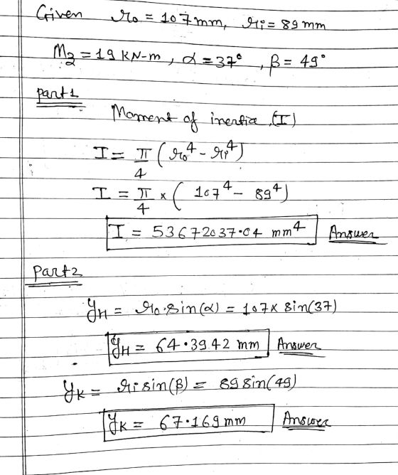
 The cross-sectional dimensions of the beam shown in the figure are r, = 115 mm and r; = 89 mm. Given M, = 20 kN.m, a = 26°, and B = 50°, what are the bending stresses at points Hand K? H a Part 1 Find the area moment of inertia for the cross-section about the Z axis. 1,= i mm e Textbook and Media Hint Save for Later Attempts: unlimited Submit Answer Part 2 Find the y coordinates of...
Problem 2) Combined Loading (30 points) The structure shown has a diameter of 40 mm. The length dimensions are a 500 mm and d -100 mm. Using load magnitudes of P.-3000 N, 1000 N, and B-1500 N, det...
 Problem 2) Combined Loading (30 points) The structure shown has a diameter of 40 mm. The length dimensions are a 500 mm and d -100 mm. Using load magnitudes of P.-3000 N, 1000 N, and B-1500 N, determine the normal and shear-stresses in the structure at point H. (Point H is co-planar with the x-y plane.) The cross-sectional properties are A 1257 mm2 J = 251,327 mm" 1,-1,-125,664 mm4 emax -5333 mm3 Present your answers in the following stress tensor...
4. (30%) For a beam with a T-section as shown, the cross-sectional dimensions of 12 mm....
 4. (30%) For a beam with a T-section as shown, the cross-sectional dimensions of 12 mm. The centroid is 75 mm, h = 90 mm, t the beam are b 60 mm, h, at C and c 30 mm. At a certain section of the beam, the bending moment is M 5.4 kN m and the vertical shear force is V= 30 kN. (a) Show that the moment of inertia of the cross-section about the z axis (the neutral axis)...
Part 1 Correct Three loads are applied to the cantilever beam shown. The cross-sectional dimensions of...
 Part 1 Correct Three loads are applied to the cantilever beam shown. The cross-sectional dimensions of the beam are shown in second figure. Assume a = 10 in, h = 2 in., k =3 in, e = 4 in., P = 26 kips, Q = 21 kips, R = 10 kips, b = 9 in., and d - 13 in (a) Determine the normal and shear stresses at point K. (b) Determine the principal stresses and maximum in-plane shear stress...
A cantilever beam supports the loads shown. The cross-sectional dimensions of the shape are also shown....
 A cantilever beam supports the loads shown. The cross-sectional dimensions of the shape are also shown. Assume mm, by - 85 mm, 5 mm, 9 mm. Determine - 0.5 m, P. - 4.0 kN, Pg - 7.5 kN, Pe-2.0 kN, -85 (a) the maximum vertical shear stress. (b) the maximum compression bending stress. (c) the maximum tension bending stress. See the coordinate system for the beam in the problem figure with the origin of the x axis at the feed...
4. A T-shaped cross-sectional beam is loaded as shown in the figure. Determine the following a....
 4. A T-shaped cross-sectional beam is loaded as shown in the figure. Determine the following a. Sketch the internal shear force and bending moment diagrams for the beam. b. Calculate the maximum magnitude of the bending stress. Indicate where this occurs on the cross-section and along the length of the beam. c. Calculate the transverse shearing stress at the centroid of the cross-section using the maximum magnitude of the transverse shear force. - 200 mm 8 KN 1.5 kN/m 20...
A tubular steel column CD supports horizontal cantilever arm ABC, as shown in the figure. Column...
 A tubular steel column CD supports horizontal cantilever arm ABC, as shown in the figure. Column CD has an outside diameter of 9.000 in. and a wall thickness of 0.460 in. The loads are PA = 300 lb and Pb = 540 lb. Dimensions of the structure are a = 6.3 ft, b= 8.0 ft, and c = 14.0 ft. Determine the maximum compression stress at the base of column CD. b a PA C B A D *Part 1...
The cantilever beam shown in the figure is subjected to a concentrated load at point B....
 The cantilever beam shown in the figure is subjected to a concentrated load at point B. The stresses acting at point H on the beam are to be determined. H Cross section For this analysis, use the following values: Beam and Load. a = 1.75 m b=0.30 m @= 60 degrees P = 25 KN Cross-sectional Dimensions d=250 mm bp = 125 mm ty=7 mm tw = 7 mm C= 30 mm (Note: The load P applied at Bacts in...
Consider the beam and loading shown. The cross-sectional area is rectangular which measures 200 mm x...
 Consider the beam and loading shown. The cross-sectional area is
rectangular which measures 200 mm x 400 mm. What is the
maximum bending stress, fbmax in MPa ? Use two decimal
places.
y 10 kN 50 kNm A с X +B 2m 3 m
Consider the beam and loading shown. The cross-sectional area is
rectangular which measures 200 mm x 400 mm. What is the
maximum bending stress, fbmax in MPa ? Use two decimal
places.
y 10 kN 50 kNm A с X +B 2m 3 m
 The cross-sectional dimensions of the beam shown in the figure are r, = 125 mm and r, = 81 mm. Given M. = 13 kN.m, a = 316, and B = 45, what are the bending stresses at points Hand K? H/ Part 1 Find the area moment of inertia for the cross-section about the z axis. I. y Part 2 Find the y coordinates of points Hand K. mm ya mm Click if you would like to Show Work...
 The cross-sectional dimensions of the beam shown in the figure are r, = 115 mm and r; = 89 mm. Given M, = 20 kN.m, a = 26°, and B = 50°, what are the bending stresses at points Hand K? H a Part 1 Find the area moment of inertia for the cross-section about the Z axis. 1,= i mm e Textbook and Media Hint Save for Later Attempts: unlimited Submit Answer Part 2 Find the y coordinates of...
 Problem 2) Combined Loading (30 points) The structure shown has a diameter of 40 mm. The length dimensions are a 500 mm and d -100 mm. Using load magnitudes of P.-3000 N, 1000 N, and B-1500 N, determine the normal and shear-stresses in the structure at point H. (Point H is co-planar with the x-y plane.) The cross-sectional properties are A 1257 mm2 J = 251,327 mm" 1,-1,-125,664 mm4 emax -5333 mm3 Present your answers in the following stress tensor...
 4. (30%) For a beam with a T-section as shown, the cross-sectional dimensions of 12 mm. The centroid is 75 mm, h = 90 mm, t the beam are b 60 mm, h, at C and c 30 mm. At a certain section of the beam, the bending moment is M 5.4 kN m and the vertical shear force is V= 30 kN. (a) Show that the moment of inertia of the cross-section about the z axis (the neutral axis)...
 Part 1 Correct Three loads are applied to the cantilever beam shown. The cross-sectional dimensions of the beam are shown in second figure. Assume a = 10 in, h = 2 in., k =3 in, e = 4 in., P = 26 kips, Q = 21 kips, R = 10 kips, b = 9 in., and d - 13 in (a) Determine the normal and shear stresses at point K. (b) Determine the principal stresses and maximum in-plane shear stress...
 A cantilever beam supports the loads shown. The cross-sectional dimensions of the shape are also shown. Assume mm, by - 85 mm, 5 mm, 9 mm. Determine - 0.5 m, P. - 4.0 kN, Pg - 7.5 kN, Pe-2.0 kN, -85 (a) the maximum vertical shear stress. (b) the maximum compression bending stress. (c) the maximum tension bending stress. See the coordinate system for the beam in the problem figure with the origin of the x axis at the feed...
 4. A T-shaped cross-sectional beam is loaded as shown in the figure. Determine the following a. Sketch the internal shear force and bending moment diagrams for the beam. b. Calculate the maximum magnitude of the bending stress. Indicate where this occurs on the cross-section and along the length of the beam. c. Calculate the transverse shearing stress at the centroid of the cross-section using the maximum magnitude of the transverse shear force. - 200 mm 8 KN 1.5 kN/m 20...
 A tubular steel column CD supports horizontal cantilever arm ABC, as shown in the figure. Column CD has an outside diameter of 9.000 in. and a wall thickness of 0.460 in. The loads are PA = 300 lb and Pb = 540 lb. Dimensions of the structure are a = 6.3 ft, b= 8.0 ft, and c = 14.0 ft. Determine the maximum compression stress at the base of column CD. b a PA C B A D *Part 1...
 The cantilever beam shown in the figure is subjected to a concentrated load at point B. The stresses acting at point H on the beam are to be determined. H Cross section For this analysis, use the following values: Beam and Load. a = 1.75 m b=0.30 m @= 60 degrees P = 25 KN Cross-sectional Dimensions d=250 mm bp = 125 mm ty=7 mm tw = 7 mm C= 30 mm (Note: The load P applied at Bacts in...
 Consider the beam and loading shown. The cross-sectional area is
rectangular which measures 200 mm x 400 mm. What is the
maximum bending stress, fbmax in MPa ? Use two decimal
places.
y 10 kN 50 kNm A с X +B 2m 3 m
Consider the beam and loading shown. The cross-sectional area is
rectangular which measures 200 mm x 400 mm. What is the
maximum bending stress, fbmax in MPa ? Use two decimal
places.
y 10 kN 50 kNm A с X +B 2m 3 m
Most questions answered within 3 hours.
-
Where is the error in this code sequence?
String s1 = "Hello";
String s2 = "ello";...
asked 11 months ago -
Financial data for Joel de Paris, Inc., for last year
follow:
Joel de Paris, Inc.
Balance...
asked 11 months ago -
Consider this reaction:
Al2(SO4)3 (aq)+ BaCl3
(aq) Al2Cl6 (aq)- +
3BaSO4(s) . What is the...
asked 11 months ago -
Suppose that Savneet is considering increasing her
recent random sample from 20 car rentals to 40...
asked 11 months ago -
Trucks arrive at an unloading terminal at an average rate of 120
per hour.
Trucks arrive...
asked 11 months ago -
Why are methanol and ethanol completely soluble in water while
octanol is not very little soluble....
asked 11 months ago -
A facilities manager at a university reads in a research report
that the mean amount of...
asked 11 months ago -
When the CuSO4 is rehydrated by adding water to the anhydrous
compound, is this an endothermic...
asked 11 months ago -
A ray of sunlight is passing from diamond into crown glass; the
angle of incidence is...
asked 11 months ago -
A block of mass 0.249 kg is placed on top of a light, vertical
spring of...
asked 11 months ago -
how do the kidneys compensate in the presences of acidosis
a) trigger hyperventilate
b) reserve acid...
asked 11 months ago -
Question 501 pts
The rental rate of capital to the firm increases. Which of the
following...
asked 11 months ago