Using the table and shape tools, draw a properly constructed UML diagram depicting the relationship among...
Using the table and shape tools, draw a properly constructed UML diagram depicting the relationship among the elements. [10 marks]
Homework Answers
Types of relationship 
Example : Bank System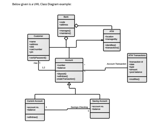
Add Answer to:
Using the table and shape tools, draw a properly constructed UML
diagram depicting the relationship among...
hello i was given an assignment on object orientated programming and we were asked to use...
 hello i was given an assignment on object orientated programming
and we were asked to use Microsoft word, Comments for significant
parts should be coloured green. And can you recommend some videos
too so i can understand it better with your help.
i
have some questions about this assignment given and was told to
create in Microsoft word
Name your file with your full name, e.g.. Jessica_Jones.docx or (arth). • Programs/codes must be properly indented and free of compile-time errors....
hello i was given an assignment on object orientated programming
and we were asked to use Microsoft word, Comments for significant
parts should be coloured green. And can you recommend some videos
too so i can understand it better with your help.
i
have some questions about this assignment given and was told to
create in Microsoft word
Name your file with your full name, e.g.. Jessica_Jones.docx or (arth). • Programs/codes must be properly indented and free of compile-time errors....
1) This exercise is about Inheritance (IS-A) Relationship. A) First, draw the UML diagram for class...
1) This exercise is about Inheritance (IS-A) Relationship. A) First, draw the UML diagram for class Student and class ComputerSystemsStudent which are described below. Make sure to show all the members (member variables and member functions) of the classes on your UML diagram. Save your UML diagram and also export it as a PNG. B) Second, write a program that contains the following parts. Write each class interface and implementation, in a different .h and .cpp file, respectively. a) Create...
2) [10] Draw a Mohr's circle diagram and the principal and shear stress elements, all properly...
 2) [10] Draw a Mohr's circle diagram and the principal and shear stress elements, all properly labeled, for the following plane stress. 0x = 20 MPa, ay = -80 MPa, Txy = -60 MPa
E/R diagram: Draw a complete Doctors office system E-R diagram using UML or crow’s foot notation...
E/R diagram: Draw a complete Doctors office system E-R diagram using UML or crow’s foot notation that includes all of the entities, attributes, identifiers. Relationships should be appropriately labeled with verb phrases. Make it neat. Once the E-R model has created, convert the E-R model to a set of relations by using rules. We will call this set of relations the initial set of relations derived from the E-R model. You use to implement your database application in MS Access....
Draw the UML DIAGRAM ALSO PLEASE DRAW THE UML DIAGRAM.ALSO in java should use the program in java For this task you will create a Point3D class to represent a point that has coordinates in thr...
 Draw the UML DIAGRAM ALSO
PLEASE DRAW THE UML DIAGRAM.ALSO
in java
should use the program in java
For this task you will create a Point3D class to represent a point that has coordinates in three dimensions labeled x, y and z. You will then use the class to perform some calculations on an array of these points. You need to draw a UML diagram for the class (Point3D) and then implement the class The Point3D class will have the...
Draw the UML DIAGRAM ALSO
PLEASE DRAW THE UML DIAGRAM.ALSO
in java
should use the program in java
For this task you will create a Point3D class to represent a point that has coordinates in three dimensions labeled x, y and z. You will then use the class to perform some calculations on an array of these points. You need to draw a UML diagram for the class (Point3D) and then implement the class The Point3D class will have the...
Control System By using the asymptotic or straight line approximation method, draw the Bode diagram for...
 Control System
By using the asymptotic or straight line approximation method, draw the Bode diagram for a control system with the open loop transfer function is given by: (b) 10 G(s)H(s)= (s+1)(s + 10) (12 marks) Analyze the stability of this control system (c) (4 marks)
By using the asymptotic or straight line approximation method, draw the Bode diagram for a control system with the open loop transfer function is given by: (b) 10 G(s)H(s)= (s+1)(s + 10) (12 marks)...
Control System
By using the asymptotic or straight line approximation method, draw the Bode diagram for a control system with the open loop transfer function is given by: (b) 10 G(s)H(s)= (s+1)(s + 10) (12 marks) Analyze the stability of this control system (c) (4 marks)
By using the asymptotic or straight line approximation method, draw the Bode diagram for a control system with the open loop transfer function is given by: (b) 10 G(s)H(s)= (s+1)(s + 10) (12 marks)...
Please use Umlet. Draw a UML domain model class diagram using the following notes on the...
Please use Umlet. Draw a UML domain model class diagram using the following notes on the classes, attributes and relationships discovered by the analyst so far: Your head analyst has been interviewing the department faculty about the course scheduler they would like to have developed. So far she has found a few classes. Your job is to create the UML Class diagram. Here is the information we have so far: Classes: • The Room class. All rooms have a building...
(10%) Draw the State Table using the above table. Is this a Mealy or Moore Model...
 (10%) Draw the State Table using the above table. Is this a
Mealy or Moore Model design?
(15%) Design a Sequential FSM machine for it, using at least 1
JK type flip flop.
(5%) Draw the Circuit diagram.
Consider the following state diagram, where states are so = 00, S1 = 01, S2 = 10 , S3 =11 1/1 Reset 1/0 1/0 0/0 C S3 1/01 0/0
(10%) Draw the State Table using the above table. Is this a
Mealy or Moore Model design?
(15%) Design a Sequential FSM machine for it, using at least 1
JK type flip flop.
(5%) Draw the Circuit diagram.
Consider the following state diagram, where states are so = 00, S1 = 01, S2 = 10 , S3 =11 1/1 Reset 1/0 1/0 0/0 C S3 1/01 0/0
Java Project Draw a class diagram for the below class (using UML notation) import java.io.BufferedReader; import...
 Java Project
Draw a class diagram for the below class (using UML
notation)
import java.io.BufferedReader;
import java.io.FileWriter;
import java.io.IOException;
import java.io.InputStreamReader;
public class myData {
public static void main(String[] args) {
String str;
BufferedReader br = new BufferedReader(new
InputStreamReader(System.in));
System.out.println("Enter text (‘stop’ to quit).");
try (FileWriter fw = new FileWriter("test.txt")) {
do {
System.out.print(": ");
str = br.readLine();
if (str.compareTo("stop") == 0)
break;
str = str + "\r\n"; // add newline
fw.write(str);
} while (str.compareTo("stop") != 0);
} catch (IOException...
Java Project
Draw a class diagram for the below class (using UML
notation)
import java.io.BufferedReader;
import java.io.FileWriter;
import java.io.IOException;
import java.io.InputStreamReader;
public class myData {
public static void main(String[] args) {
String str;
BufferedReader br = new BufferedReader(new
InputStreamReader(System.in));
System.out.println("Enter text (‘stop’ to quit).");
try (FileWriter fw = new FileWriter("test.txt")) {
do {
System.out.print(": ");
str = br.readLine();
if (str.compareTo("stop") == 0)
break;
str = str + "\r\n"; // add newline
fw.write(str);
} while (str.compareTo("stop") != 0);
} catch (IOException...
Create a truth table to implement AND logic using only NAND gates. Draw the circuit diagram...
Create a truth table to implement AND logic using only NAND gates. Draw the circuit diagram (schematic) for the implementation. Do the same for OR logic using only NOR gates.
 hello i was given an assignment on object orientated programming
and we were asked to use Microsoft word, Comments for significant
parts should be coloured green. And can you recommend some videos
too so i can understand it better with your help.
i
have some questions about this assignment given and was told to
create in Microsoft word
Name your file with your full name, e.g.. Jessica_Jones.docx or (arth). • Programs/codes must be properly indented and free of compile-time errors....
hello i was given an assignment on object orientated programming
and we were asked to use Microsoft word, Comments for significant
parts should be coloured green. And can you recommend some videos
too so i can understand it better with your help.
i
have some questions about this assignment given and was told to
create in Microsoft word
Name your file with your full name, e.g.. Jessica_Jones.docx or (arth). • Programs/codes must be properly indented and free of compile-time errors....
 2) [10] Draw a Mohr's circle diagram and the principal and shear stress elements, all properly labeled, for the following plane stress. 0x = 20 MPa, ay = -80 MPa, Txy = -60 MPa
 Draw the UML DIAGRAM ALSO
PLEASE DRAW THE UML DIAGRAM.ALSO
in java
should use the program in java
For this task you will create a Point3D class to represent a point that has coordinates in three dimensions labeled x, y and z. You will then use the class to perform some calculations on an array of these points. You need to draw a UML diagram for the class (Point3D) and then implement the class The Point3D class will have the...
Draw the UML DIAGRAM ALSO
PLEASE DRAW THE UML DIAGRAM.ALSO
in java
should use the program in java
For this task you will create a Point3D class to represent a point that has coordinates in three dimensions labeled x, y and z. You will then use the class to perform some calculations on an array of these points. You need to draw a UML diagram for the class (Point3D) and then implement the class The Point3D class will have the...
 Control System
By using the asymptotic or straight line approximation method, draw the Bode diagram for a control system with the open loop transfer function is given by: (b) 10 G(s)H(s)= (s+1)(s + 10) (12 marks) Analyze the stability of this control system (c) (4 marks)
By using the asymptotic or straight line approximation method, draw the Bode diagram for a control system with the open loop transfer function is given by: (b) 10 G(s)H(s)= (s+1)(s + 10) (12 marks)...
Control System
By using the asymptotic or straight line approximation method, draw the Bode diagram for a control system with the open loop transfer function is given by: (b) 10 G(s)H(s)= (s+1)(s + 10) (12 marks) Analyze the stability of this control system (c) (4 marks)
By using the asymptotic or straight line approximation method, draw the Bode diagram for a control system with the open loop transfer function is given by: (b) 10 G(s)H(s)= (s+1)(s + 10) (12 marks)...
 (10%) Draw the State Table using the above table. Is this a
Mealy or Moore Model design?
(15%) Design a Sequential FSM machine for it, using at least 1
JK type flip flop.
(5%) Draw the Circuit diagram.
Consider the following state diagram, where states are so = 00, S1 = 01, S2 = 10 , S3 =11 1/1 Reset 1/0 1/0 0/0 C S3 1/01 0/0
(10%) Draw the State Table using the above table. Is this a
Mealy or Moore Model design?
(15%) Design a Sequential FSM machine for it, using at least 1
JK type flip flop.
(5%) Draw the Circuit diagram.
Consider the following state diagram, where states are so = 00, S1 = 01, S2 = 10 , S3 =11 1/1 Reset 1/0 1/0 0/0 C S3 1/01 0/0
 Java Project
Draw a class diagram for the below class (using UML
notation)
import java.io.BufferedReader;
import java.io.FileWriter;
import java.io.IOException;
import java.io.InputStreamReader;
public class myData {
public static void main(String[] args) {
String str;
BufferedReader br = new BufferedReader(new
InputStreamReader(System.in));
System.out.println("Enter text (‘stop’ to quit).");
try (FileWriter fw = new FileWriter("test.txt")) {
do {
System.out.print(": ");
str = br.readLine();
if (str.compareTo("stop") == 0)
break;
str = str + "\r\n"; // add newline
fw.write(str);
} while (str.compareTo("stop") != 0);
} catch (IOException...
Java Project
Draw a class diagram for the below class (using UML
notation)
import java.io.BufferedReader;
import java.io.FileWriter;
import java.io.IOException;
import java.io.InputStreamReader;
public class myData {
public static void main(String[] args) {
String str;
BufferedReader br = new BufferedReader(new
InputStreamReader(System.in));
System.out.println("Enter text (‘stop’ to quit).");
try (FileWriter fw = new FileWriter("test.txt")) {
do {
System.out.print(": ");
str = br.readLine();
if (str.compareTo("stop") == 0)
break;
str = str + "\r\n"; // add newline
fw.write(str);
} while (str.compareTo("stop") != 0);
} catch (IOException...
Most questions answered within 3 hours.
-
Where is the error in this code sequence?
String s1 = "Hello";
String s2 = "ello";...
asked 10 months ago -
Financial data for Joel de Paris, Inc., for last year
follow:
Joel de Paris, Inc.
Balance...
asked 10 months ago -
Consider this reaction:
Al2(SO4)3 (aq)+ BaCl3
(aq) Al2Cl6 (aq)- +
3BaSO4(s) . What is the...
asked 10 months ago -
Suppose that Savneet is considering increasing her
recent random sample from 20 car rentals to 40...
asked 10 months ago -
Trucks arrive at an unloading terminal at an average rate of 120
per hour.
Trucks arrive...
asked 10 months ago -
Why are methanol and ethanol completely soluble in water while
octanol is not very little soluble....
asked 10 months ago -
A facilities manager at a university reads in a research report
that the mean amount of...
asked 10 months ago -
When the CuSO4 is rehydrated by adding water to the anhydrous
compound, is this an endothermic...
asked 10 months ago -
A ray of sunlight is passing from diamond into crown glass; the
angle of incidence is...
asked 10 months ago -
A block of mass 0.249 kg is placed on top of a light, vertical
spring of...
asked 10 months ago -
how do the kidneys compensate in the presences of acidosis
a) trigger hyperventilate
b) reserve acid...
asked 10 months ago -
Question 501 pts
The rental rate of capital to the firm increases. Which of the
following...
asked 10 months ago