Please use the method of the left and right end internal force
and moment of each section. Thanks.
Homework Answers

Add Answer to:
Please use the method of the left and right end internal force
and moment of each...
Problem 5.1: This is a similar problem of 5.44 in the book (7 edition), however, you...
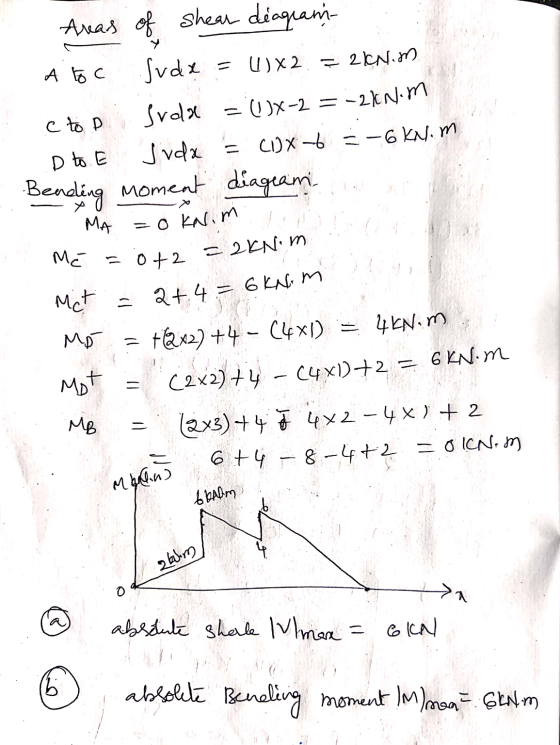
 Problem 5.1: This is a similar problem of 5.44 in the book (7 edition), however, you are required to draw the shear and bending-moment diagrams based on the method of the left and right end internal force and moment of each section PROBLEM 5.44 Draw the shear and bending-moment diagrams for the beam and loading shown, and determine the maximum absolute value (a) of the shear, (b) of the bending moment B 4 IN Imm 0.5m. Problem 5.2: This is...
This is a similar problem of 5.5 in the book (7th edition), however, you are required...
 This is a similar problem of 5.5 in the book (7th edition), however, you are required to draw the shear and bending-moment diagrams based on x function internal force and moment in each section PROBLEM 5.5 ВІ С A For the beam and loading shown, (a) draw the shear and bending-moment diagrams, (b) determine the equations of the shear and bending-moment curves.
Diagram on the right (5.10) using integration method to find equations of shear force and bending...
 Diagram on the right (5.10)
using integration method to find equations of shear force and
bending moment.
5.10 Draw the shear and bending-moment diagrams for the beam and loading shown, and determine the maximum absolute value (a) of the shear, (b) of the bending moment. 2.5 kips/it 15 kips 25 kN/m с D D B B 40 KN 40 KN 6 ft 3 ft 6 ft too 1.8 m 0.6 m Fig. P5.10 0.6 m Fig. P5.9
Diagram on the right (5.10)
using integration method to find equations of shear force and
bending moment.
5.10 Draw the shear and bending-moment diagrams for the beam and loading shown, and determine the maximum absolute value (a) of the shear, (b) of the bending moment. 2.5 kips/it 15 kips 25 kN/m с D D B B 40 KN 40 KN 6 ft 3 ft 6 ft too 1.8 m 0.6 m Fig. P5.10 0.6 m Fig. P5.9
Use the graphical method to construct the shear-force and bending-moment diagrams for the beam shown.
 Use the graphical method to construct the shear-force and bending-moment diagrams for the beam shown. Label all significant points on each diagram and identify the maximum moments along with their respective locations. For all answers entered, use the sign convention for shear forces and bending moments. (a) Find the location x and the corresponding bending moment M at the one point between A and B at which the shear force equals zero. (b) Consider the entire beam and determine the maximum positive...
Use the graphical method to construct the shear-force and bending-moment diagrams for the beam shown. Label...
 Use the graphical method to construct the shear-force and bending-moment diagrams for the beam shown. Label all significant points on each diagram and identify the maximum moments along with their respective locations. For all answers entered, use the sign convention for shear forces and bending moments (a) Find the location x and the corresponding bending moment M at the one point between A and D at which the shear force equals zero. (b) Consider the entire beam and determine the...
4. For the beam and loading shown, draw the shear force and bending moment diagrams and...
 4. For the beam and loading shown, draw the shear force and bending moment diagrams and determine the maximum bending and shear force and their locations. 20 KN 40 KN B D 250 mm |--2.5 m- 3m-4-2 m 80 mm 5. For the beam and loading shown, draw the shear force and bending moment diagrams and determine the maximum bending and shear force and their locations. 50 KN
Problem 5.4: This is a similar problem of 5.43 in the book (7th edition), however, you...
 Problem 5.4: This is a similar problem of 5.43 in the book (7th edition), however, you are required to draw the shear and bending-moment diagrams based on the method of load, shear and bending moment relationship. 2.5 kipsit 15 kips D PROBLEM 5.43 Using the method of Sec. 5.2. solve Prob. 5.10. PROBLEM 5.10 Draw the shear and bending-moment diagrams for the beam and loading shown, and determine the maximum absolute value (a) of the shear, (b) of the bending...
mechanics of materials , book- beer and johnson, ch-5 Problem 5.5: This is a similar problem...
 mechanics of materials , book- beer and johnson,
ch-5
Problem 5.5: This is a similar problem of 5.65 in the book (7th edition), when you draw the shear and bending- moment diagrams, you can use anyone you prefer for. 1.8 KN 3.6 kN 40 mm PROBLEM 5.65 For the beam and loading shown, design the cross section of the beam, knowing that the grade of timber used has an allowable normal stress of 12 MPa. 0.5 m 0.8 m OS...
mechanics of materials , book- beer and johnson,
ch-5
Problem 5.5: This is a similar problem of 5.65 in the book (7th edition), when you draw the shear and bending- moment diagrams, you can use anyone you prefer for. 1.8 KN 3.6 kN 40 mm PROBLEM 5.65 For the beam and loading shown, design the cross section of the beam, knowing that the grade of timber used has an allowable normal stress of 12 MPa. 0.5 m 0.8 m OS...
Problem 5.3: This is a similar problem of 5.41 in the book (7th edition), however, you...
 Problem 5.3: This is a similar problem of 5.41 in the book (7th edition), however, you are required to draw the shear and bending-moment diagrams based on the method of load, shear and bending moment relationship 100I PROBLEM 5.41 Using the method of Sec. 5.2. solve Prob. 5.8. PROBLEM 5.8 Draw the shear and bending-moment diagrams for the beam and loading shown, and determine the maximum absolute value (a) of the shear. (b) of the bending moment. 100 lb 250...
 Problem 5.1: This is a similar problem of 5.44 in the book (7 edition), however, you are required to draw the shear and bending-moment diagrams based on the method of the left and right end internal force and moment of each section PROBLEM 5.44 Draw the shear and bending-moment diagrams for the beam and loading shown, and determine the maximum absolute value (a) of the shear, (b) of the bending moment B 4 IN Imm 0.5m. Problem 5.2: This is...
 This is a similar problem of 5.5 in the book (7th edition), however, you are required to draw the shear and bending-moment diagrams based on x function internal force and moment in each section PROBLEM 5.5 ВІ С A For the beam and loading shown, (a) draw the shear and bending-moment diagrams, (b) determine the equations of the shear and bending-moment curves.
 Diagram on the right (5.10)
using integration method to find equations of shear force and
bending moment.
5.10 Draw the shear and bending-moment diagrams for the beam and loading shown, and determine the maximum absolute value (a) of the shear, (b) of the bending moment. 2.5 kips/it 15 kips 25 kN/m с D D B B 40 KN 40 KN 6 ft 3 ft 6 ft too 1.8 m 0.6 m Fig. P5.10 0.6 m Fig. P5.9
Diagram on the right (5.10)
using integration method to find equations of shear force and
bending moment.
5.10 Draw the shear and bending-moment diagrams for the beam and loading shown, and determine the maximum absolute value (a) of the shear, (b) of the bending moment. 2.5 kips/it 15 kips 25 kN/m с D D B B 40 KN 40 KN 6 ft 3 ft 6 ft too 1.8 m 0.6 m Fig. P5.10 0.6 m Fig. P5.9
 Use the graphical method to construct the shear-force and bending-moment diagrams for the beam shown. Label all significant points on each diagram and identify the maximum moments along with their respective locations. For all answers entered, use the sign convention for shear forces and bending moments. (a) Find the location x and the corresponding bending moment M at the one point between A and B at which the shear force equals zero. (b) Consider the entire beam and determine the maximum positive...
 Use the graphical method to construct the shear-force and bending-moment diagrams for the beam shown. Label all significant points on each diagram and identify the maximum moments along with their respective locations. For all answers entered, use the sign convention for shear forces and bending moments (a) Find the location x and the corresponding bending moment M at the one point between A and D at which the shear force equals zero. (b) Consider the entire beam and determine the...
 4. For the beam and loading shown, draw the shear force and bending moment diagrams and determine the maximum bending and shear force and their locations. 20 KN 40 KN B D 250 mm |--2.5 m- 3m-4-2 m 80 mm 5. For the beam and loading shown, draw the shear force and bending moment diagrams and determine the maximum bending and shear force and their locations. 50 KN
 Problem 5.4: This is a similar problem of 5.43 in the book (7th edition), however, you are required to draw the shear and bending-moment diagrams based on the method of load, shear and bending moment relationship. 2.5 kipsit 15 kips D PROBLEM 5.43 Using the method of Sec. 5.2. solve Prob. 5.10. PROBLEM 5.10 Draw the shear and bending-moment diagrams for the beam and loading shown, and determine the maximum absolute value (a) of the shear, (b) of the bending...
 Problem 5.4: This is a similar problem of 5.43 in the book (7th edition), however, you are required to draw the shear and bending-moment diagrams based on the method of load, shear and bending moment relationship. 2.5 kipsit 15 kips D PROBLEM 5.43 Using the method of Sec. 5.2. solve Prob. 5.10. PROBLEM 5.10 Draw the shear and bending-moment diagrams for the beam and loading shown, and determine the maximum absolute value (a) of the shear, (b) of the bending...
 mechanics of materials , book- beer and johnson,
ch-5
Problem 5.5: This is a similar problem of 5.65 in the book (7th edition), when you draw the shear and bending- moment diagrams, you can use anyone you prefer for. 1.8 KN 3.6 kN 40 mm PROBLEM 5.65 For the beam and loading shown, design the cross section of the beam, knowing that the grade of timber used has an allowable normal stress of 12 MPa. 0.5 m 0.8 m OS...
mechanics of materials , book- beer and johnson,
ch-5
Problem 5.5: This is a similar problem of 5.65 in the book (7th edition), when you draw the shear and bending- moment diagrams, you can use anyone you prefer for. 1.8 KN 3.6 kN 40 mm PROBLEM 5.65 For the beam and loading shown, design the cross section of the beam, knowing that the grade of timber used has an allowable normal stress of 12 MPa. 0.5 m 0.8 m OS...
 Problem 5.3: This is a similar problem of 5.41 in the book (7th edition), however, you are required to draw the shear and bending-moment diagrams based on the method of load, shear and bending moment relationship 100I PROBLEM 5.41 Using the method of Sec. 5.2. solve Prob. 5.8. PROBLEM 5.8 Draw the shear and bending-moment diagrams for the beam and loading shown, and determine the maximum absolute value (a) of the shear. (b) of the bending moment. 100 lb 250...
Most questions answered within 3 hours.
-
Where is the error in this code sequence?
String s1 = "Hello";
String s2 = "ello";...
asked 10 months ago -
Financial data for Joel de Paris, Inc., for last year
follow:
Joel de Paris, Inc.
Balance...
asked 10 months ago -
Consider this reaction:
Al2(SO4)3 (aq)+ BaCl3
(aq) Al2Cl6 (aq)- +
3BaSO4(s) . What is the...
asked 10 months ago -
Suppose that Savneet is considering increasing her
recent random sample from 20 car rentals to 40...
asked 10 months ago -
Trucks arrive at an unloading terminal at an average rate of 120
per hour.
Trucks arrive...
asked 10 months ago -
Why are methanol and ethanol completely soluble in water while
octanol is not very little soluble....
asked 10 months ago -
A facilities manager at a university reads in a research report
that the mean amount of...
asked 10 months ago -
When the CuSO4 is rehydrated by adding water to the anhydrous
compound, is this an endothermic...
asked 10 months ago -
A ray of sunlight is passing from diamond into crown glass; the
angle of incidence is...
asked 10 months ago -
A block of mass 0.249 kg is placed on top of a light, vertical
spring of...
asked 10 months ago -
how do the kidneys compensate in the presences of acidosis
a) trigger hyperventilate
b) reserve acid...
asked 10 months ago -
Question 501 pts
The rental rate of capital to the firm increases. Which of the
following...
asked 10 months ago