
Homework Answers
The solution is provided in the images below. Revert back in case of any query.


Add Answer to:
the
required data is there , just need to caslculate it
Week 8, Question 1: For...
For the truss shown in the following figure, the temperature of member BC is raised by...
 For
the truss shown in the following figure, the temperature of member
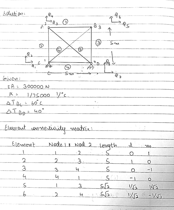
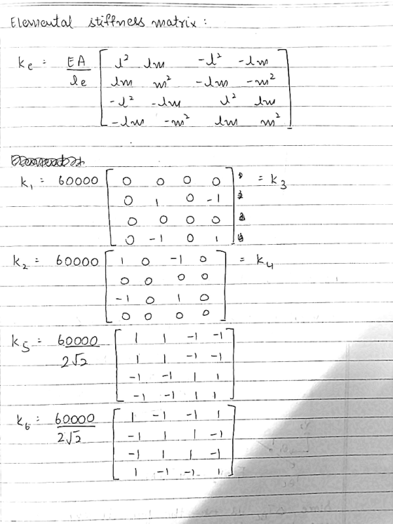
BC is raised by 50 ∘C, and member BD is raised by 80 ∘C. EA= 300000
N for all members and α= 1/75000 1/∘C. Use the stiffness method to
do the following:
Week 8, Question 1: For the truss shown in the following figure, the temperature of member BC is raised by 50 °C, and member BD is raised by 80 °C. EA= 300000 N for all members...
For
the truss shown in the following figure, the temperature of member
BC is raised by 50 ∘C, and member BD is raised by 80 ∘C. EA= 300000
N for all members and α= 1/75000 1/∘C. Use the stiffness method to
do the following:
Week 8, Question 1: For the truss shown in the following figure, the temperature of member BC is raised by 50 °C, and member BD is raised by 80 °C. EA= 300000 N for all members...
For the truss shown in the following figure, the temperature of member BC is raised by...
 For the truss shown in the following figure, the temperature of member BC is raised by 10 °C, and member BD is raised by 150 °C. EA= 300000 N for all members and a= 1/75000 1/°C. Use the st do the following: А B 5 m A с D 5 m Part 1. Calculate the displacements at the joints: a) Ax = mm b) Ay = mm c) B. = mm d) B = mm e) Ct = mm Part...
Week 8, Question 2: Member AC of the following truss is subjected to a temperature change...
 Week 8, Question 2: Member AC of the following truss is subjected to a temperature change of +80 °C. Calculate the displacements of node A and the forces in each member using the stiffness method. Take: a= 2x 10⁻⁵; EA= 2x 10⁴ kN; the cross section area of AC as A; the cross section area of AD as A 2; the cross section area of AB as 1A. 1.732 m I'm kim Part 1. The displacements at joint A: a)...
Week 8, Question 2: Member AC of the following truss is subjected to a temperature change...
 Week 8, Question 2: Member AC of the following truss is subjected to a temperature change of +50 °C. Calculate the displacements of node A and the forces in each member using the stiffness method. Take: a= 2x 10⁻⁵; EA= 2x 10⁴ kN; the cross section area of AC as A; the cross section area of AD as AV2; the cross section area of AB as 1A. B 1.732 m A 1 m D 1 m Part 1. The displacements...
Week 8, Question 2: Member AC of the following truss is subjected to a temperature change...
 Week 8, Question 2: Member AC of the following truss is subjected to a temperature change of +50 °C. Calculate the displacements of node A and the forces in each member using the stiffness method. Take: a= 2x 10⁻⁵; EA= 2x 10⁴ kN; the cross section area of AC as A; the cross section area of AD as AV2; the cross section area of AB as 2.0A. B 1.732 m 1 m D Part 1. The displacements at joint A:...
Truss ABCD is simply supported at joints A and C. Force F = 100 N and...
 Truss ABCD is simply supported at joints A and C. Force F = 100 N and acts downward at joint D. Length AB = BC = 4m and length BD = 3m. Determine the force (N) acting in member BD and its direction. (use +### for tension and -### for compression). D B A С F
Week 7. Question 1: Use the stiffness method to determine the horizontal and vertical displacements at...
 Week 7. Question 1: Use the stiffness method to determine the horizontal and vertical displacements at joint A. For all members, E-206.8 GPa and A - 1290 mm? Take a - 8 mandb-6.1 m B 2 انها 160 kN Solve the problem by following these steps Part 1) Calculate the stiffness matrix of each member in the global coordinate system. Check kna (the value at the second column and second row) in each member stiffness matrix a) Member 1: ky...
i need help with c and d but explain why Question 1 (10 marks). Assembly A model consists of two 1D trusses with dimens...
 i need help with c and d but explain why
Question 1 (10 marks). Assembly A model consists of two 1D trusses with dimensions as given in Figure 1. Element 1 runs angle, connecting parallel to the x-axis, connecting node 1 and 2. Element 2 is running at an node 1 and 3. Node 1 has an applied force in the negative y-direction. Node 1 can only in y-direction, while nodes 2 and 3 are fixed in both x and...
i need help with c and d but explain why
Question 1 (10 marks). Assembly A model consists of two 1D trusses with dimensions as given in Figure 1. Element 1 runs angle, connecting parallel to the x-axis, connecting node 1 and 2. Element 2 is running at an node 1 and 3. Node 1 has an applied force in the negative y-direction. Node 1 can only in y-direction, while nodes 2 and 3 are fixed in both x and...
Week 9. Question 1: Use the stiffness method to analyse the structure shown below. For the...
 Week 9. Question 1: Use the stiffness method to analyse the structure shown below. For the beam ABC, E = 2 -10% kPa, A -00, = 1.2e - 4 m. For the truss member DB, E = 200000000 kPa, A = 0.002 m. Also, take L54 m and w37 kN/m с 7 Degrees of freedom 22 Calculate the the bending moment at Joint B following the steps below. Part 1: Assemble the global structure stiffness matrix. Note that ABC is...
Week 9, Question 1: Use the stiffness method to analyse the structure shown below. For the...
 Week 9, Question 1: Use the stiffness method to analyse the structure shown below. For the beam ABC, E = 2-108 kPa, A=00, I = 1.2e - 4 mº.. For the truss member DB, E = 200000000 kPa, A=0.002 m2. Also, take L=6.9 m and w=30 kN/m. Degrees of freedom l- _-2L Calculate the the bending moment at Joint B following the steps below: Part 1: Assemble the global structure stiffness matrix. Note that ABC is infinitely rigid in the...
 For
the truss shown in the following figure, the temperature of member
BC is raised by 50 ∘C, and member BD is raised by 80 ∘C. EA= 300000
N for all members and α= 1/75000 1/∘C. Use the stiffness method to
do the following:
Week 8, Question 1: For the truss shown in the following figure, the temperature of member BC is raised by 50 °C, and member BD is raised by 80 °C. EA= 300000 N for all members...
For
the truss shown in the following figure, the temperature of member
BC is raised by 50 ∘C, and member BD is raised by 80 ∘C. EA= 300000
N for all members and α= 1/75000 1/∘C. Use the stiffness method to
do the following:
Week 8, Question 1: For the truss shown in the following figure, the temperature of member BC is raised by 50 °C, and member BD is raised by 80 °C. EA= 300000 N for all members...
 For the truss shown in the following figure, the temperature of member BC is raised by 10 °C, and member BD is raised by 150 °C. EA= 300000 N for all members and a= 1/75000 1/°C. Use the st do the following: А B 5 m A с D 5 m Part 1. Calculate the displacements at the joints: a) Ax = mm b) Ay = mm c) B. = mm d) B = mm e) Ct = mm Part...
 Week 8, Question 2: Member AC of the following truss is subjected to a temperature change of +80 °C. Calculate the displacements of node A and the forces in each member using the stiffness method. Take: a= 2x 10⁻⁵; EA= 2x 10⁴ kN; the cross section area of AC as A; the cross section area of AD as A 2; the cross section area of AB as 1A. 1.732 m I'm kim Part 1. The displacements at joint A: a)...
 Week 8, Question 2: Member AC of the following truss is subjected to a temperature change of +50 °C. Calculate the displacements of node A and the forces in each member using the stiffness method. Take: a= 2x 10⁻⁵; EA= 2x 10⁴ kN; the cross section area of AC as A; the cross section area of AD as AV2; the cross section area of AB as 1A. B 1.732 m A 1 m D 1 m Part 1. The displacements...
 Week 8, Question 2: Member AC of the following truss is subjected to a temperature change of +50 °C. Calculate the displacements of node A and the forces in each member using the stiffness method. Take: a= 2x 10⁻⁵; EA= 2x 10⁴ kN; the cross section area of AC as A; the cross section area of AD as AV2; the cross section area of AB as 2.0A. B 1.732 m 1 m D Part 1. The displacements at joint A:...
 Truss ABCD is simply supported at joints A and C. Force F = 100 N and acts downward at joint D. Length AB = BC = 4m and length BD = 3m. Determine the force (N) acting in member BD and its direction. (use +### for tension and -### for compression). D B A С F
 Week 7. Question 1: Use the stiffness method to determine the horizontal and vertical displacements at joint A. For all members, E-206.8 GPa and A - 1290 mm? Take a - 8 mandb-6.1 m B 2 انها 160 kN Solve the problem by following these steps Part 1) Calculate the stiffness matrix of each member in the global coordinate system. Check kna (the value at the second column and second row) in each member stiffness matrix a) Member 1: ky...
 i need help with c and d but explain why
Question 1 (10 marks). Assembly A model consists of two 1D trusses with dimensions as given in Figure 1. Element 1 runs angle, connecting parallel to the x-axis, connecting node 1 and 2. Element 2 is running at an node 1 and 3. Node 1 has an applied force in the negative y-direction. Node 1 can only in y-direction, while nodes 2 and 3 are fixed in both x and...
i need help with c and d but explain why
Question 1 (10 marks). Assembly A model consists of two 1D trusses with dimensions as given in Figure 1. Element 1 runs angle, connecting parallel to the x-axis, connecting node 1 and 2. Element 2 is running at an node 1 and 3. Node 1 has an applied force in the negative y-direction. Node 1 can only in y-direction, while nodes 2 and 3 are fixed in both x and...
 Week 9. Question 1: Use the stiffness method to analyse the structure shown below. For the beam ABC, E = 2 -10% kPa, A -00, = 1.2e - 4 m. For the truss member DB, E = 200000000 kPa, A = 0.002 m. Also, take L54 m and w37 kN/m с 7 Degrees of freedom 22 Calculate the the bending moment at Joint B following the steps below. Part 1: Assemble the global structure stiffness matrix. Note that ABC is...
 Week 9, Question 1: Use the stiffness method to analyse the structure shown below. For the beam ABC, E = 2-108 kPa, A=00, I = 1.2e - 4 mº.. For the truss member DB, E = 200000000 kPa, A=0.002 m2. Also, take L=6.9 m and w=30 kN/m. Degrees of freedom l- _-2L Calculate the the bending moment at Joint B following the steps below: Part 1: Assemble the global structure stiffness matrix. Note that ABC is infinitely rigid in the...
Most questions answered within 3 hours.
-
Where is the error in this code sequence?
String s1 = "Hello";
String s2 = "ello";...
asked 10 months ago -
Financial data for Joel de Paris, Inc., for last year
follow:
Joel de Paris, Inc.
Balance...
asked 10 months ago -
Consider this reaction:
Al2(SO4)3 (aq)+ BaCl3
(aq) Al2Cl6 (aq)- +
3BaSO4(s) . What is the...
asked 10 months ago -
Suppose that Savneet is considering increasing her
recent random sample from 20 car rentals to 40...
asked 10 months ago -
Trucks arrive at an unloading terminal at an average rate of 120
per hour.
Trucks arrive...
asked 10 months ago -
Why are methanol and ethanol completely soluble in water while
octanol is not very little soluble....
asked 10 months ago -
A facilities manager at a university reads in a research report
that the mean amount of...
asked 10 months ago -
When the CuSO4 is rehydrated by adding water to the anhydrous
compound, is this an endothermic...
asked 10 months ago -
A ray of sunlight is passing from diamond into crown glass; the
angle of incidence is...
asked 10 months ago -
A block of mass 0.249 kg is placed on top of a light, vertical
spring of...
asked 10 months ago -
how do the kidneys compensate in the presences of acidosis
a) trigger hyperventilate
b) reserve acid...
asked 10 months ago -
Question 501 pts
The rental rate of capital to the firm increases. Which of the
following...
asked 10 months ago