
Homework Answers
Ans 1) Comparison between Open Loop and closed loop control Sytem


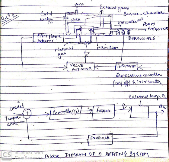
Ans2) Block diagram representation of heating system
Ans 3) The function of ratio controller or ratio control is to control the other flow so as to maintain the desired ratio between the two flows. The flow controlled by the ratio controller is called the controlled flow. There many examples of ratio control .
For example, treatment of drinking water with chlorine, where we want the controlled flow of chlorine in the wild flow of water.
Another example is ratio control used in the production of paint, where a base liquid must be mixed with one or more pigments to achieve a desired consistency and color.
Add Answer to:
MECH641- Process Instrumentation and Control (Assignment 3) Answer the following: (Each Question carries 5 marks) 1....
Answer the following: (Each Question carries 5 marks) 1. Design a Hydraulic circuit and electrohydraulic circuit...
 Answer the following: (Each Question carries 5 marks) 1. Design a Hydraulic circuit and electrohydraulic circuit for the Scissors Platform Lift. 2. Explain the concept of controlling electrical circuit remotely. 3. Critically explain the working of the crane with respect to the hydraulic circuit drawn. Main boom M Load Booming cylinder Counterbalance valve MB MX Main valve - Reducing valve w Pressure relief valve MA AI Joystick BI K2 T Directional control valve KI Main pump Make-up Check pump valve...
Q. 1 (5 marks) For the system in Fig. (a). Assume proportion control, Gc(s)-K, sketch the root lo...
 pls answer dont just copy other solution or ur catching a
dislike
Q. 1 (5 marks) For the system in Fig. (a). Assume proportion control, Gc(s)-K, sketch the root locus for the closed-loop system (b). Using the angle condition, prove that s12 +j2 is not on the root locus. (c). Design a lead compensator Ge(s) - K such that the dominant closed-loop poles are located at s1--2 2. (d), What are the zero and pole of lead compensator G() (e)....
pls answer dont just copy other solution or ur catching a
dislike
Q. 1 (5 marks) For the system in Fig. (a). Assume proportion control, Gc(s)-K, sketch the root locus for the closed-loop system (b). Using the angle condition, prove that s12 +j2 is not on the root locus. (c). Design a lead compensator Ge(s) - K such that the dominant closed-loop poles are located at s1--2 2. (d), What are the zero and pole of lead compensator G() (e)....
Question 1 a) Define the term transfer function in relation to a linear control system. [5...
 Question 1 a) Define the term transfer function in relation to a
linear control system. [5 marks] Figure Q1 shows a block diagram of
a feedback control system, with a plant with transfer function G(s)
, a controller with transfer function C(s) , and a sensor with
transfer function H(s) . b) Derive from first principles the closed
loop transfer function G (s) cl from the reference signal r(t) , to
the output signal y(t) . [5 marks] c) Give...
Question 1 a) Define the term transfer function in relation to a
linear control system. [5 marks] Figure Q1 shows a block diagram of
a feedback control system, with a plant with transfer function G(s)
, a controller with transfer function C(s) , and a sensor with
transfer function H(s) . b) Derive from first principles the closed
loop transfer function G (s) cl from the reference signal r(t) , to
the output signal y(t) . [5 marks] c) Give...
This is Process Control & Instrumentation Questions. Kindly help to show me the calculation (step by step) and including correct answer. Thanks a lot. Find the approximation change in a metal wire...
 This is Process Control & Instrumentation
Questions. Kindly help to show me the calculation (step by step)
and including correct answer. Thanks a lot.
Find the approximation change in a metal wire of resistance 100 Ω that results from a strain of 1200 μm/m. Use the given formula (3 marks) (d) ΔΙ A total of 70 Kg of metal is put on a conveyor system with a speed of 120 m/min. Determine the flow rate (expressed in Kg/h) of the...
This is Process Control & Instrumentation
Questions. Kindly help to show me the calculation (step by step)
and including correct answer. Thanks a lot.
Find the approximation change in a metal wire of resistance 100 Ω that results from a strain of 1200 μm/m. Use the given formula (3 marks) (d) ΔΙ A total of 70 Kg of metal is put on a conveyor system with a speed of 120 m/min. Determine the flow rate (expressed in Kg/h) of the...
Convert following the transfer function into state space representation (Marks 5) 3 +45² T($) = 54...
 Convert following the transfer function into state space representation (Marks 5) 3 +45² T($) = 54 +52 +7 Convert the following state space into a transfer function. (Marks 5) x = 11 * = x + ( u 21 y = [02]x + [2]u Evaluate the steady-state error of state-space system. (Marks 5) i [ 10] [21. *= 15 2]* +11 y = [ 02]x + [2]u Evaluate the steady-state error of state-space system. (Marks 5) -1 0x+lu x =...
Question 4 A control system is shown in Figure 3, where Ge(s) is the controller, R(s)...
 Question 4 A control system is shown in Figure 3, where Ge(s) is the controller, R(s) is the setpoint temperature, Tw is the measured water temperature, Ta is the ambient temperature and u(t) is the rate of heat supplied to the heater. The mathematical model of a simple thermal system consisting of an insulated tank of water is given by: dTW = c(1, - Iw) +u dt where c is the heat insulation coefficient. Heater Water R(s) Ta Gc/s) u(1)...
pls answer dont just copy other solution or ur catching a dislike Q. 1 (5 marks)...
 pls answer dont just copy other solution or ur catching a
dislike
Q. 1 (5 marks) For the system in Fig. (a). Assume proportion control, Gc(s)-K, sketch the root locus for the closed-loop system (b). Using the angle condition, prove that s12 +j2 is not on the root locus. (c). Design a lead compensator Ge(s) - K such that the dominant closed-loop poles are located at s1--2 2. (d), What are the zero and pole of lead compensator G() (e)....
pls answer dont just copy other solution or ur catching a
dislike
Q. 1 (5 marks) For the system in Fig. (a). Assume proportion control, Gc(s)-K, sketch the root locus for the closed-loop system (b). Using the angle condition, prove that s12 +j2 is not on the root locus. (c). Design a lead compensator Ge(s) - K such that the dominant closed-loop poles are located at s1--2 2. (d), What are the zero and pole of lead compensator G() (e)....
Question 1 For the following closed-loop control system, identify the element/signal for each number: 1 5...
 Question 1 For the following closed-loop control system, identify the element/signal for each number: 1 5 3 6 oo Actuator 9 7 4 N. A. Desired Output 2 B. Actual Output 3 C. Error 4 D. Sensor 5 E. Controller F. Plant G. Manipulated variable H. Measured Output Control Input
I am stuck on how to create the transfer function to be suitable for a bide plot, then actually plotting the Bode diagram Question 3 A third order process is to be controlled by a proportional con...
 I am stuck on how to create the transfer function to
be suitable for a bide plot, then actually plotting the Bode
diagram
Question 3 A third order process is to be controlled by a proportional controller (Kp) and is to havea unity feedback closed loop arrangement. The process consists of three first order lags that have the following parameters GP1-1s+1) GP2 8/(s+2) GP3 5(s+0.2) A) Draw the system closed block diagram 3 marks B) Using the Log-Linear graph paper...
I am stuck on how to create the transfer function to
be suitable for a bide plot, then actually plotting the Bode
diagram
Question 3 A third order process is to be controlled by a proportional controller (Kp) and is to havea unity feedback closed loop arrangement. The process consists of three first order lags that have the following parameters GP1-1s+1) GP2 8/(s+2) GP3 5(s+0.2) A) Draw the system closed block diagram 3 marks B) Using the Log-Linear graph paper...
Question 3 A high quality telescope is represented using a transfer function, shown in Figure 3. It needs to follow a trajectory described by input E(s) exactly in order to track a star. The outp...
 Question 3 A high quality telescope is represented using a transfer function, shown in Figure 3. It needs to follow a trajectory described by input E(s) exactly in order to track a star. The output C(s) is the angle of the telescope E(s) 7 C) Figure 3: A System expressed as a Transfer Function (a) Convert the system into state space form (b) Find the steady state error when a unity step input is applied. (c) Is your answer to...
 Answer the following: (Each Question carries 5 marks) 1. Design a Hydraulic circuit and electrohydraulic circuit for the Scissors Platform Lift. 2. Explain the concept of controlling electrical circuit remotely. 3. Critically explain the working of the crane with respect to the hydraulic circuit drawn. Main boom M Load Booming cylinder Counterbalance valve MB MX Main valve - Reducing valve w Pressure relief valve MA AI Joystick BI K2 T Directional control valve KI Main pump Make-up Check pump valve...
 pls answer dont just copy other solution or ur catching a
dislike
Q. 1 (5 marks) For the system in Fig. (a). Assume proportion control, Gc(s)-K, sketch the root locus for the closed-loop system (b). Using the angle condition, prove that s12 +j2 is not on the root locus. (c). Design a lead compensator Ge(s) - K such that the dominant closed-loop poles are located at s1--2 2. (d), What are the zero and pole of lead compensator G() (e)....
pls answer dont just copy other solution or ur catching a
dislike
Q. 1 (5 marks) For the system in Fig. (a). Assume proportion control, Gc(s)-K, sketch the root locus for the closed-loop system (b). Using the angle condition, prove that s12 +j2 is not on the root locus. (c). Design a lead compensator Ge(s) - K such that the dominant closed-loop poles are located at s1--2 2. (d), What are the zero and pole of lead compensator G() (e)....
 Question 1 a) Define the term transfer function in relation to a
linear control system. [5 marks] Figure Q1 shows a block diagram of
a feedback control system, with a plant with transfer function G(s)
, a controller with transfer function C(s) , and a sensor with
transfer function H(s) . b) Derive from first principles the closed
loop transfer function G (s) cl from the reference signal r(t) , to
the output signal y(t) . [5 marks] c) Give...
Question 1 a) Define the term transfer function in relation to a
linear control system. [5 marks] Figure Q1 shows a block diagram of
a feedback control system, with a plant with transfer function G(s)
, a controller with transfer function C(s) , and a sensor with
transfer function H(s) . b) Derive from first principles the closed
loop transfer function G (s) cl from the reference signal r(t) , to
the output signal y(t) . [5 marks] c) Give...
 This is Process Control & Instrumentation
Questions. Kindly help to show me the calculation (step by step)
and including correct answer. Thanks a lot.
Find the approximation change in a metal wire of resistance 100 Ω that results from a strain of 1200 μm/m. Use the given formula (3 marks) (d) ΔΙ A total of 70 Kg of metal is put on a conveyor system with a speed of 120 m/min. Determine the flow rate (expressed in Kg/h) of the...
This is Process Control & Instrumentation
Questions. Kindly help to show me the calculation (step by step)
and including correct answer. Thanks a lot.
Find the approximation change in a metal wire of resistance 100 Ω that results from a strain of 1200 μm/m. Use the given formula (3 marks) (d) ΔΙ A total of 70 Kg of metal is put on a conveyor system with a speed of 120 m/min. Determine the flow rate (expressed in Kg/h) of the...
 Convert following the transfer function into state space representation (Marks 5) 3 +45² T($) = 54 +52 +7 Convert the following state space into a transfer function. (Marks 5) x = 11 * = x + ( u 21 y = [02]x + [2]u Evaluate the steady-state error of state-space system. (Marks 5) i [ 10] [21. *= 15 2]* +11 y = [ 02]x + [2]u Evaluate the steady-state error of state-space system. (Marks 5) -1 0x+lu x =...
 Question 4 A control system is shown in Figure 3, where Ge(s) is the controller, R(s) is the setpoint temperature, Tw is the measured water temperature, Ta is the ambient temperature and u(t) is the rate of heat supplied to the heater. The mathematical model of a simple thermal system consisting of an insulated tank of water is given by: dTW = c(1, - Iw) +u dt where c is the heat insulation coefficient. Heater Water R(s) Ta Gc/s) u(1)...
 pls answer dont just copy other solution or ur catching a
dislike
Q. 1 (5 marks) For the system in Fig. (a). Assume proportion control, Gc(s)-K, sketch the root locus for the closed-loop system (b). Using the angle condition, prove that s12 +j2 is not on the root locus. (c). Design a lead compensator Ge(s) - K such that the dominant closed-loop poles are located at s1--2 2. (d), What are the zero and pole of lead compensator G() (e)....
pls answer dont just copy other solution or ur catching a
dislike
Q. 1 (5 marks) For the system in Fig. (a). Assume proportion control, Gc(s)-K, sketch the root locus for the closed-loop system (b). Using the angle condition, prove that s12 +j2 is not on the root locus. (c). Design a lead compensator Ge(s) - K such that the dominant closed-loop poles are located at s1--2 2. (d), What are the zero and pole of lead compensator G() (e)....
 Question 1 For the following closed-loop control system, identify the element/signal for each number: 1 5 3 6 oo Actuator 9 7 4 N. A. Desired Output 2 B. Actual Output 3 C. Error 4 D. Sensor 5 E. Controller F. Plant G. Manipulated variable H. Measured Output Control Input
 I am stuck on how to create the transfer function to
be suitable for a bide plot, then actually plotting the Bode
diagram
Question 3 A third order process is to be controlled by a proportional controller (Kp) and is to havea unity feedback closed loop arrangement. The process consists of three first order lags that have the following parameters GP1-1s+1) GP2 8/(s+2) GP3 5(s+0.2) A) Draw the system closed block diagram 3 marks B) Using the Log-Linear graph paper...
I am stuck on how to create the transfer function to
be suitable for a bide plot, then actually plotting the Bode
diagram
Question 3 A third order process is to be controlled by a proportional controller (Kp) and is to havea unity feedback closed loop arrangement. The process consists of three first order lags that have the following parameters GP1-1s+1) GP2 8/(s+2) GP3 5(s+0.2) A) Draw the system closed block diagram 3 marks B) Using the Log-Linear graph paper...
 Question 3 A high quality telescope is represented using a transfer function, shown in Figure 3. It needs to follow a trajectory described by input E(s) exactly in order to track a star. The output C(s) is the angle of the telescope E(s) 7 C) Figure 3: A System expressed as a Transfer Function (a) Convert the system into state space form (b) Find the steady state error when a unity step input is applied. (c) Is your answer to...
Most questions answered within 3 hours.
-
Where is the error in this code sequence?
String s1 = "Hello";
String s2 = "ello";...
asked 11 months ago -
Financial data for Joel de Paris, Inc., for last year
follow:
Joel de Paris, Inc.
Balance...
asked 11 months ago -
Consider this reaction:
Al2(SO4)3 (aq)+ BaCl3
(aq) Al2Cl6 (aq)- +
3BaSO4(s) . What is the...
asked 11 months ago -
Suppose that Savneet is considering increasing her
recent random sample from 20 car rentals to 40...
asked 11 months ago -
Trucks arrive at an unloading terminal at an average rate of 120
per hour.
Trucks arrive...
asked 11 months ago -
Why are methanol and ethanol completely soluble in water while
octanol is not very little soluble....
asked 11 months ago -
A facilities manager at a university reads in a research report
that the mean amount of...
asked 11 months ago -
When the CuSO4 is rehydrated by adding water to the anhydrous
compound, is this an endothermic...
asked 11 months ago -
A ray of sunlight is passing from diamond into crown glass; the
angle of incidence is...
asked 11 months ago -
A block of mass 0.249 kg is placed on top of a light, vertical
spring of...
asked 11 months ago -
how do the kidneys compensate in the presences of acidosis
a) trigger hyperventilate
b) reserve acid...
asked 11 months ago -
Question 501 pts
The rental rate of capital to the firm increases. Which of the
following...
asked 11 months ago