


Homework Answers
Add Answer to:
Question 4 (Marks: 15) A circuit you were using has been adjusted to provide a load...
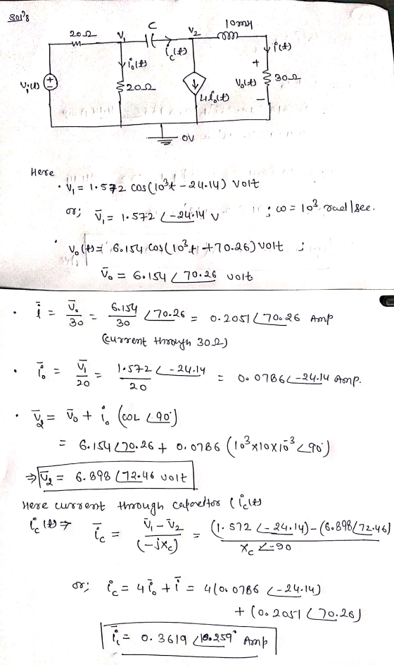
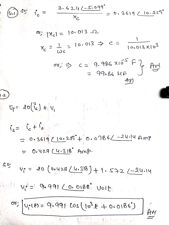
EET315 Netwi -2019 Winter 4. Using Laplace Transform to calculate Vo(t) for the following circuit, and power supply V=10 volts; all the rest components (capacitor, resistor, inductor) are represe...
 EET315 Netwi -2019 Winter 4. Using Laplace Transform to calculate Vo(t) for the following circuit, and power supply V=10 volts; all the rest components (capacitor, resistor, inductor) are represented by C, R and L T-O Volt)
EET315 Netwi -2019 Winter 4. Using Laplace Transform to calculate Vo(t) for the following circuit, and power supply V=10 volts; all the rest components (capacitor, resistor, inductor) are represented by C, R and L T-O Volt)
EET315 Netwi -2019 Winter 4. Using Laplace Transform to calculate Vo(t) for the following circuit, and power supply V=10 volts; all the rest components (capacitor, resistor, inductor) are represented by C, R and L T-O Volt)
19, 20 2020 Question 2 (Marks: 15) You are performing a practical experiment with the circuit...
 19, 20 2020 Question 2 (Marks: 15) You are performing a practical experiment with the circuit in figure 2a. You have performed all your calculations but at the end you notice that the voltage source does not give you 115cos(t) Volts but 121.cos(t + 8) Volts. You do not want to redo all your calculations so instead you decide to insert an impedance Zx into the circuit as in figure2b to balance out the voltage. 1Ω 1Ω 1Ω ZX 1Ω...
Consider the following circuit. a) Using any method you want, calculate Vo(t) given Vi(t) = u(t)...
 Consider the following circuit.
a) Using any method you want, calculate Vo(t) given Vi(t) =
u(t) for the following circuit and plot as a function of
time.
b) Calcualte Vo(t) when Vi(t) = e^(j2(pi)ft) and plot the
magnitude ans phase as a function of f.
pts) Q.1) Consider the following circuit. 2 H o,(t) 3 2 (15 pts) Using any method you want, calculate vo(t) given v(t)-u() for the following circuit and plot as a function of time. (15 pts)...
Consider the following circuit.
a) Using any method you want, calculate Vo(t) given Vi(t) =
u(t) for the following circuit and plot as a function of
time.
b) Calcualte Vo(t) when Vi(t) = e^(j2(pi)ft) and plot the
magnitude ans phase as a function of f.
pts) Q.1) Consider the following circuit. 2 H o,(t) 3 2 (15 pts) Using any method you want, calculate vo(t) given v(t)-u() for the following circuit and plot as a function of time. (15 pts)...
QUESTION 5 (15 points) a. You have a power supply which is a full-wave rectifier with a capacitor filter. It operates f...
 QUESTION 5 (15 points) a. You have a power supply which is a full-wave rectifier with a capacitor filter. It operates from the mains and provides an output of Voc-20 V with 20% ripple, when the load current is 2 A Calculate the maximum and minimum values of the output waveform of this power supply. b. Now you will design a series voltage regulator between the power supply described in part (a) and an electronic device operating at 12 VDC...
We calculated the capacticance of our capacitior in farads and we have to compare it to...
 We
calculated the capacticance of our capacitior in farads and we have
to compare it to the listed capacitance of the capacitor as shown
in the picture. When we do percent difference we get 200%... where
did I mess up? That can't be right. The resistance of our resistor
is 12970 ohms. Please explain this like you were talking to a
child.
Amicon 26936KO (M) 2000 F25V 81-POLAR NPS wire leads of the resistor to the table the body of...
We
calculated the capacticance of our capacitior in farads and we have
to compare it to the listed capacitance of the capacitor as shown
in the picture. When we do percent difference we get 200%... where
did I mess up? That can't be right. The resistance of our resistor
is 12970 ohms. Please explain this like you were talking to a
child.
Amicon 26936KO (M) 2000 F25V 81-POLAR NPS wire leads of the resistor to the table the body of...
The class E inverter as shown in Figure 7-1 operates at resonance and has Vs-48 V and R-10 Ω The ...
 The class E inverter as shown in Figure 7-1 operates at resonance and has Vs-48 V and R-10 Ω The switching frequency is fs- 20 kHz. Assume a quality factor Q-7. (a) Calculate the parameters and complete Table 7-1. Assume an ideal transistor switch the optimum values on inductor / the optimum value of capacitor C the optimum values on inductor Le the optimum value of capacitor Ce the damping factor δ the peak output voltage Vo for Vi= 12...
please help answer question 4, a-f please using the data below from chart 1 objectives from...
 please help answer question 4, a-f please
using the data below from chart 1
objectives from lab, thank you
DATA:CA y 3 Ay No3 Part I: Cell Potential of voltaic cells under standard conditions: cell CU CND2 #27 14.0m Give the half Half cell reaction at Combinations Oxidation Reduction E the anode and with [ion] takes place Theoretical takes place cathode. Write in M here here (V) above the arrow E c (V) if it is oxidation or reduction. |-0.340...
please help answer question 4, a-f please
using the data below from chart 1
objectives from lab, thank you
DATA:CA y 3 Ay No3 Part I: Cell Potential of voltaic cells under standard conditions: cell CU CND2 #27 14.0m Give the half Half cell reaction at Combinations Oxidation Reduction E the anode and with [ion] takes place Theoretical takes place cathode. Write in M here here (V) above the arrow E c (V) if it is oxidation or reduction. |-0.340...
I only need help with the discussion there are many info that you do not need put I put just in ...
 I only need help with the discussion
there are many info that you do not need put I put just in
case as well as my data table.
please do it as soon as u can
Meauements ODeit1 Check2 Meaurements Checi3 Ced Check5 Check6 Measurements Check7 heck8 4058 33 536 1502 1035 979 119478 041 1.0319|0.554972| 64261| 153|15542033681 995781 5266566 1578807 298h 1631 119 1209430016 079096812 0.418135246 0,00032665 011890:004668155728441 0293237 1.291809502 1.22833 1.28 1952 -1116 4281 140616885511984206317 3346 8162 0.78...
I only need help with the discussion
there are many info that you do not need put I put just in
case as well as my data table.
please do it as soon as u can
Meauements ODeit1 Check2 Meaurements Checi3 Ced Check5 Check6 Measurements Check7 heck8 4058 33 536 1502 1035 979 119478 041 1.0319|0.554972| 64261| 153|15542033681 995781 5266566 1578807 298h 1631 119 1209430016 079096812 0.418135246 0,00032665 011890:004668155728441 0293237 1.291809502 1.22833 1.28 1952 -1116 4281 140616885511984206317 3346 8162 0.78...
 EET315 Netwi -2019 Winter 4. Using Laplace Transform to calculate Vo(t) for the following circuit, and power supply V=10 volts; all the rest components (capacitor, resistor, inductor) are represented by C, R and L T-O Volt)
EET315 Netwi -2019 Winter 4. Using Laplace Transform to calculate Vo(t) for the following circuit, and power supply V=10 volts; all the rest components (capacitor, resistor, inductor) are represented by C, R and L T-O Volt)
EET315 Netwi -2019 Winter 4. Using Laplace Transform to calculate Vo(t) for the following circuit, and power supply V=10 volts; all the rest components (capacitor, resistor, inductor) are represented by C, R and L T-O Volt)
 19, 20 2020 Question 2 (Marks: 15) You are performing a practical experiment with the circuit in figure 2a. You have performed all your calculations but at the end you notice that the voltage source does not give you 115cos(t) Volts but 121.cos(t + 8) Volts. You do not want to redo all your calculations so instead you decide to insert an impedance Zx into the circuit as in figure2b to balance out the voltage. 1Ω 1Ω 1Ω ZX 1Ω...
 Consider the following circuit.
a) Using any method you want, calculate Vo(t) given Vi(t) =
u(t) for the following circuit and plot as a function of
time.
b) Calcualte Vo(t) when Vi(t) = e^(j2(pi)ft) and plot the
magnitude ans phase as a function of f.
pts) Q.1) Consider the following circuit. 2 H o,(t) 3 2 (15 pts) Using any method you want, calculate vo(t) given v(t)-u() for the following circuit and plot as a function of time. (15 pts)...
Consider the following circuit.
a) Using any method you want, calculate Vo(t) given Vi(t) =
u(t) for the following circuit and plot as a function of
time.
b) Calcualte Vo(t) when Vi(t) = e^(j2(pi)ft) and plot the
magnitude ans phase as a function of f.
pts) Q.1) Consider the following circuit. 2 H o,(t) 3 2 (15 pts) Using any method you want, calculate vo(t) given v(t)-u() for the following circuit and plot as a function of time. (15 pts)...
 QUESTION 5 (15 points) a. You have a power supply which is a full-wave rectifier with a capacitor filter. It operates from the mains and provides an output of Voc-20 V with 20% ripple, when the load current is 2 A Calculate the maximum and minimum values of the output waveform of this power supply. b. Now you will design a series voltage regulator between the power supply described in part (a) and an electronic device operating at 12 VDC...
 We
calculated the capacticance of our capacitior in farads and we have
to compare it to the listed capacitance of the capacitor as shown
in the picture. When we do percent difference we get 200%... where
did I mess up? That can't be right. The resistance of our resistor
is 12970 ohms. Please explain this like you were talking to a
child.
Amicon 26936KO (M) 2000 F25V 81-POLAR NPS wire leads of the resistor to the table the body of...
We
calculated the capacticance of our capacitior in farads and we have
to compare it to the listed capacitance of the capacitor as shown
in the picture. When we do percent difference we get 200%... where
did I mess up? That can't be right. The resistance of our resistor
is 12970 ohms. Please explain this like you were talking to a
child.
Amicon 26936KO (M) 2000 F25V 81-POLAR NPS wire leads of the resistor to the table the body of...
 The class E inverter as shown in Figure 7-1 operates at resonance and has Vs-48 V and R-10 Ω The switching frequency is fs- 20 kHz. Assume a quality factor Q-7. (a) Calculate the parameters and complete Table 7-1. Assume an ideal transistor switch the optimum values on inductor / the optimum value of capacitor C the optimum values on inductor Le the optimum value of capacitor Ce the damping factor δ the peak output voltage Vo for Vi= 12...
 please help answer question 4, a-f please
using the data below from chart 1
objectives from lab, thank you
DATA:CA y 3 Ay No3 Part I: Cell Potential of voltaic cells under standard conditions: cell CU CND2 #27 14.0m Give the half Half cell reaction at Combinations Oxidation Reduction E the anode and with [ion] takes place Theoretical takes place cathode. Write in M here here (V) above the arrow E c (V) if it is oxidation or reduction. |-0.340...
please help answer question 4, a-f please
using the data below from chart 1
objectives from lab, thank you
DATA:CA y 3 Ay No3 Part I: Cell Potential of voltaic cells under standard conditions: cell CU CND2 #27 14.0m Give the half Half cell reaction at Combinations Oxidation Reduction E the anode and with [ion] takes place Theoretical takes place cathode. Write in M here here (V) above the arrow E c (V) if it is oxidation or reduction. |-0.340...
 I only need help with the discussion
there are many info that you do not need put I put just in
case as well as my data table.
please do it as soon as u can
Meauements ODeit1 Check2 Meaurements Checi3 Ced Check5 Check6 Measurements Check7 heck8 4058 33 536 1502 1035 979 119478 041 1.0319|0.554972| 64261| 153|15542033681 995781 5266566 1578807 298h 1631 119 1209430016 079096812 0.418135246 0,00032665 011890:004668155728441 0293237 1.291809502 1.22833 1.28 1952 -1116 4281 140616885511984206317 3346 8162 0.78...
I only need help with the discussion
there are many info that you do not need put I put just in
case as well as my data table.
please do it as soon as u can
Meauements ODeit1 Check2 Meaurements Checi3 Ced Check5 Check6 Measurements Check7 heck8 4058 33 536 1502 1035 979 119478 041 1.0319|0.554972| 64261| 153|15542033681 995781 5266566 1578807 298h 1631 119 1209430016 079096812 0.418135246 0,00032665 011890:004668155728441 0293237 1.291809502 1.22833 1.28 1952 -1116 4281 140616885511984206317 3346 8162 0.78...
Most questions answered within 3 hours.
-
Where is the error in this code sequence?
String s1 = "Hello";
String s2 = "ello";...
asked 10 months ago -
Financial data for Joel de Paris, Inc., for last year
follow:
Joel de Paris, Inc.
Balance...
asked 10 months ago -
Consider this reaction:
Al2(SO4)3 (aq)+ BaCl3
(aq) Al2Cl6 (aq)- +
3BaSO4(s) . What is the...
asked 10 months ago -
Suppose that Savneet is considering increasing her
recent random sample from 20 car rentals to 40...
asked 10 months ago -
Trucks arrive at an unloading terminal at an average rate of 120
per hour.
Trucks arrive...
asked 10 months ago -
Why are methanol and ethanol completely soluble in water while
octanol is not very little soluble....
asked 10 months ago -
A facilities manager at a university reads in a research report
that the mean amount of...
asked 10 months ago -
When the CuSO4 is rehydrated by adding water to the anhydrous
compound, is this an endothermic...
asked 10 months ago -
A ray of sunlight is passing from diamond into crown glass; the
angle of incidence is...
asked 10 months ago -
A block of mass 0.249 kg is placed on top of a light, vertical
spring of...
asked 10 months ago -
how do the kidneys compensate in the presences of acidosis
a) trigger hyperventilate
b) reserve acid...
asked 10 months ago -
Question 501 pts
The rental rate of capital to the firm increases. Which of the
following...
asked 10 months ago