
Homework Answers


Add Answer to:
Values of v()/V = -1/ IR + (1)/V V R T 21 31 0.36788 0.13534 0.04979...
R t = i(t) C 2011P E e p gP a P9.09 10ed The voltage applied...
 R t = i(t) C 2011P E e p gP a P9.09 10ed The voltage applied to this circuit at t 0 (when the switch closes) is v (t) = 75 cos (4,000t - 60°) Volts Also given that R = 400 2 (0hm) and L=75 mH (milli Henry) The initial inductor current is zero for t< 0 The textbook gives you the total response equation as: )_ ?(0-¢)so R2+(w L) Cos(wt+¢-e) -V V m i(t)=itransient(t)+isteady.state(t)=R2 +(wL m - ㅎCOS...
QUESTION Cyril the Circuit Analyst is examining the interaction of both AC and DC sources with a circuit. The circu...
 QUESTION Cyril the Circuit Analyst is examining the interaction of both AC and DC sources with a circuit. The circuit is drawn below. Pay careful attention to the arrows on the switches which show which are initially open, and which are initially closed. Assume that the capacitor is initially discharged at 0. All times are in seconds 10 mH 1-Os1-1s!=2s \ t = 5s 400 | 10cos(ox) 50 pF 10 mA At 0, the first switch closes connecting the current...
- Switch S Switch S2 42 х. 42 t 0 t-0 100u(t 1F + 4H 20)...
 - Switch S Switch S2 42 х. 42 t 0 t-0 100u(t 1F + 4H 20) 40) LOOP 2 LOOP1 Figure 1 0. Before switch St closes, no energy is Switch S2 stays open while switch St closes at t stored in the inductor or capacitor. Namely-i (0- ) = uc ( 0) = 0. (a.) (10 points) Find i(t) when switch S, closes but switch S2 stays open. (b.) (10 points) After a long time or after an appropriate...
V (t) Inductor (L) esistor (R) Let L = 0.1 H, Rı-8Q, R2-100, and V(t) = 120 V. Find the currents ...
 Please provide every step in the procedure.Thanks
V (t) Inductor (L) esistor (R) Let L = 0.1 H, Rı-8Q, R2-100, and V(t) = 120 V. Find the currents on the resistors as a function of time after the switch s is closed. You may use the following system and assume (O) 20)0: , di Lat + R14 = V(t) di where i = i1 + i2. Express the system in terms of the currents i1 and i2 and solve it...
Please provide every step in the procedure.Thanks
V (t) Inductor (L) esistor (R) Let L = 0.1 H, Rı-8Q, R2-100, and V(t) = 120 V. Find the currents on the resistors as a function of time after the switch s is closed. You may use the following system and assume (O) 20)0: , di Lat + R14 = V(t) di where i = i1 + i2. Express the system in terms of the currents i1 and i2 and solve it...
Your turn: Solve for i1(t) in the following third-order circuit. Assume that the circuit was in d...
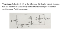 Your turn: Solve for i1(t) in the following third-order circuit. Assume that the circuit was in dc steady-state at the instance just before the switch opens. Plot the response. IH ln C. 3
Your turn: Solve for i1(t) in the following third-order circuit. Assume that the circuit was in dc steady-state at the instance just before the switch opens. Plot the response. IH ln C. 3
Your turn: Solve for i1(t) in the following third-order circuit. Assume that the circuit was in dc steady-state at the instance just before the switch opens. Plot the response. IH ln C. 3
Ri Sw Sw2R (a) Circuit Swi Closed + Open T t (ms) 10 20 30 40...
 Ri Sw Sw2R (a) Circuit Swi Closed + Open T t (ms) 10 20 30 40 50 Sw2 Closed (ms) 10 20 30 40 50 Figure m5.3 Voltage waveform for Problem m5.3. m5.3 Response of the RC Circuit: Figure m5.3(a) shows a resistor-capacitor circuit with a pair of switches and Fig. m5.3(b) shows the switch opening-closing behavior a function of time. The initial capacitor voltage is as -9 V. Component values are R1-10k. R2-3.3 kg2. (a) Determine the equation that...
“Before the switch closes” The circuit is at steady state before the switch opens at time...
 “Before the switch closes”
The circuit is at steady state before the switch opens at time t-. The input to the circuit is the vol tage of the voltage source, 12 V. The output of this circuit is the voltage across the capacitor,v() Determine v() for t>0. Show al work. 10k2 12 V
“Before the switch closes”
The circuit is at steady state before the switch opens at time t-. The input to the circuit is the vol tage of the voltage source, 12 V. The output of this circuit is the voltage across the capacitor,v() Determine v() for t>0. Show al work. 10k2 12 V
solve without laplace transform Solve for the opamp output voltage (v(t) for t> 0. Assume the circuit is in steady-state before t-0 and that all node voltages before the switch closes are zero. 1n...
 solve without laplace transform
Solve for the opamp output voltage (v(t) for t> 0. Assume the circuit is in steady-state before t-0 and that all node voltages before the switch closes are zero. 1nF 1nF v(t) t-0 v(t)
Solve for the opamp output voltage (v(t) for t> 0. Assume the circuit is in steady-state before t-0 and that all node voltages before the switch closes are zero. 1nF 1nF v(t) t-0 v(t)
solve without laplace transform
Solve for the opamp output voltage (v(t) for t> 0. Assume the circuit is in steady-state before t-0 and that all node voltages before the switch closes are zero. 1nF 1nF v(t) t-0 v(t)
Solve for the opamp output voltage (v(t) for t> 0. Assume the circuit is in steady-state before t-0 and that all node voltages before the switch closes are zero. 1nF 1nF v(t) t-0 v(t)
Please solve this second-order op amp circuit without using the laplace transform. Solve for the opamp output voltage (v(t) for t> 0. Assume the circuit is in steady-state before 0 and that all...
 Please solve this second-order op amp circuit without using
the laplace transform.
Solve for the opamp output voltage (v(t) for t> 0. Assume the circuit is in steady-state before 0 and that all node voltages before the switch closes are zero. 1nF 1nF v(t) t-0 v(t) -
Solve for the opamp output voltage (v(t) for t> 0. Assume the circuit is in steady-state before 0 and that all node voltages before the switch closes are zero. 1nF 1nF v(t) t-0...
Please solve this second-order op amp circuit without using
the laplace transform.
Solve for the opamp output voltage (v(t) for t> 0. Assume the circuit is in steady-state before 0 and that all node voltages before the switch closes are zero. 1nF 1nF v(t) t-0 v(t) -
Solve for the opamp output voltage (v(t) for t> 0. Assume the circuit is in steady-state before 0 and that all node voltages before the switch closes are zero. 1nF 1nF v(t) t-0...
 R t = i(t) C 2011P E e p gP a P9.09 10ed The voltage applied to this circuit at t 0 (when the switch closes) is v (t) = 75 cos (4,000t - 60°) Volts Also given that R = 400 2 (0hm) and L=75 mH (milli Henry) The initial inductor current is zero for t< 0 The textbook gives you the total response equation as: )_ ?(0-¢)so R2+(w L) Cos(wt+¢-e) -V V m i(t)=itransient(t)+isteady.state(t)=R2 +(wL m - ㅎCOS...
 QUESTION Cyril the Circuit Analyst is examining the interaction of both AC and DC sources with a circuit. The circuit is drawn below. Pay careful attention to the arrows on the switches which show which are initially open, and which are initially closed. Assume that the capacitor is initially discharged at 0. All times are in seconds 10 mH 1-Os1-1s!=2s \ t = 5s 400 | 10cos(ox) 50 pF 10 mA At 0, the first switch closes connecting the current...
 - Switch S Switch S2 42 х. 42 t 0 t-0 100u(t 1F + 4H 20) 40) LOOP 2 LOOP1 Figure 1 0. Before switch St closes, no energy is Switch S2 stays open while switch St closes at t stored in the inductor or capacitor. Namely-i (0- ) = uc ( 0) = 0. (a.) (10 points) Find i(t) when switch S, closes but switch S2 stays open. (b.) (10 points) After a long time or after an appropriate...
 Please provide every step in the procedure.Thanks
V (t) Inductor (L) esistor (R) Let L = 0.1 H, Rı-8Q, R2-100, and V(t) = 120 V. Find the currents on the resistors as a function of time after the switch s is closed. You may use the following system and assume (O) 20)0: , di Lat + R14 = V(t) di where i = i1 + i2. Express the system in terms of the currents i1 and i2 and solve it...
Please provide every step in the procedure.Thanks
V (t) Inductor (L) esistor (R) Let L = 0.1 H, Rı-8Q, R2-100, and V(t) = 120 V. Find the currents on the resistors as a function of time after the switch s is closed. You may use the following system and assume (O) 20)0: , di Lat + R14 = V(t) di where i = i1 + i2. Express the system in terms of the currents i1 and i2 and solve it...
 Your turn: Solve for i1(t) in the following third-order circuit. Assume that the circuit was in dc steady-state at the instance just before the switch opens. Plot the response. IH ln C. 3
Your turn: Solve for i1(t) in the following third-order circuit. Assume that the circuit was in dc steady-state at the instance just before the switch opens. Plot the response. IH ln C. 3
Your turn: Solve for i1(t) in the following third-order circuit. Assume that the circuit was in dc steady-state at the instance just before the switch opens. Plot the response. IH ln C. 3
 Ri Sw Sw2R (a) Circuit Swi Closed + Open T t (ms) 10 20 30 40 50 Sw2 Closed (ms) 10 20 30 40 50 Figure m5.3 Voltage waveform for Problem m5.3. m5.3 Response of the RC Circuit: Figure m5.3(a) shows a resistor-capacitor circuit with a pair of switches and Fig. m5.3(b) shows the switch opening-closing behavior a function of time. The initial capacitor voltage is as -9 V. Component values are R1-10k. R2-3.3 kg2. (a) Determine the equation that...
 “Before the switch closes”
The circuit is at steady state before the switch opens at time t-. The input to the circuit is the vol tage of the voltage source, 12 V. The output of this circuit is the voltage across the capacitor,v() Determine v() for t>0. Show al work. 10k2 12 V
“Before the switch closes”
The circuit is at steady state before the switch opens at time t-. The input to the circuit is the vol tage of the voltage source, 12 V. The output of this circuit is the voltage across the capacitor,v() Determine v() for t>0. Show al work. 10k2 12 V
 solve without laplace transform
Solve for the opamp output voltage (v(t) for t> 0. Assume the circuit is in steady-state before t-0 and that all node voltages before the switch closes are zero. 1nF 1nF v(t) t-0 v(t)
Solve for the opamp output voltage (v(t) for t> 0. Assume the circuit is in steady-state before t-0 and that all node voltages before the switch closes are zero. 1nF 1nF v(t) t-0 v(t)
solve without laplace transform
Solve for the opamp output voltage (v(t) for t> 0. Assume the circuit is in steady-state before t-0 and that all node voltages before the switch closes are zero. 1nF 1nF v(t) t-0 v(t)
Solve for the opamp output voltage (v(t) for t> 0. Assume the circuit is in steady-state before t-0 and that all node voltages before the switch closes are zero. 1nF 1nF v(t) t-0 v(t)
 Please solve this second-order op amp circuit without using
the laplace transform.
Solve for the opamp output voltage (v(t) for t> 0. Assume the circuit is in steady-state before 0 and that all node voltages before the switch closes are zero. 1nF 1nF v(t) t-0 v(t) -
Solve for the opamp output voltage (v(t) for t> 0. Assume the circuit is in steady-state before 0 and that all node voltages before the switch closes are zero. 1nF 1nF v(t) t-0...
Please solve this second-order op amp circuit without using
the laplace transform.
Solve for the opamp output voltage (v(t) for t> 0. Assume the circuit is in steady-state before 0 and that all node voltages before the switch closes are zero. 1nF 1nF v(t) t-0 v(t) -
Solve for the opamp output voltage (v(t) for t> 0. Assume the circuit is in steady-state before 0 and that all node voltages before the switch closes are zero. 1nF 1nF v(t) t-0...
Most questions answered within 3 hours.
-
Where is the error in this code sequence?
String s1 = "Hello";
String s2 = "ello";...
asked 11 months ago -
Financial data for Joel de Paris, Inc., for last year
follow:
Joel de Paris, Inc.
Balance...
asked 11 months ago -
Consider this reaction:
Al2(SO4)3 (aq)+ BaCl3
(aq) Al2Cl6 (aq)- +
3BaSO4(s) . What is the...
asked 11 months ago -
Suppose that Savneet is considering increasing her
recent random sample from 20 car rentals to 40...
asked 11 months ago -
Trucks arrive at an unloading terminal at an average rate of 120
per hour.
Trucks arrive...
asked 11 months ago -
Why are methanol and ethanol completely soluble in water while
octanol is not very little soluble....
asked 11 months ago -
A facilities manager at a university reads in a research report
that the mean amount of...
asked 11 months ago -
When the CuSO4 is rehydrated by adding water to the anhydrous
compound, is this an endothermic...
asked 11 months ago -
A ray of sunlight is passing from diamond into crown glass; the
angle of incidence is...
asked 11 months ago -
A block of mass 0.249 kg is placed on top of a light, vertical
spring of...
asked 11 months ago -
how do the kidneys compensate in the presences of acidosis
a) trigger hyperventilate
b) reserve acid...
asked 11 months ago -
Question 501 pts
The rental rate of capital to the firm increases. Which of the
following...
asked 11 months ago