
Homework Answers

Add Answer to:
PLEASE HELP!
Jan. 31, 2018 Name: Section: I. Consider the circuit shown in figure (a) Write...
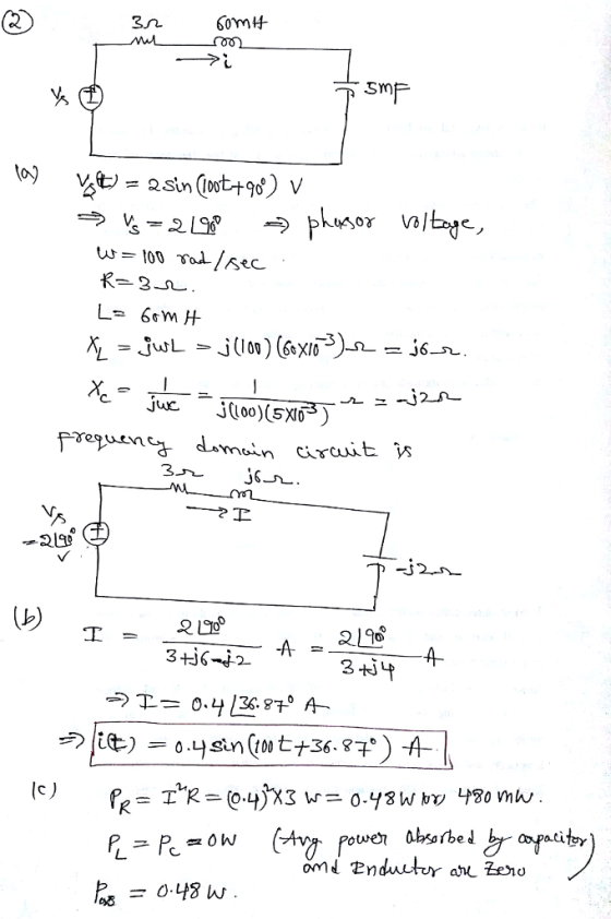
Name: Section: Jan. 31, 2018 1. Consider the circuit shown in figure 1 (a) Write the...
 Name: Section: Jan. 31, 2018 1. Consider the circuit shown in figure 1 (a) Write the mesh-current equations for the circuit. DO NOT SOLVE. (b) Write the node.voltage equations for the cireuit. DO NOT SOLVE 2. Consider the circuit shown in figure 2. The sinusoidal source is v,(04 sin (100t+90) volts (a) Transform the circuit to the frequency domain. (b) Use phasors with the mesh-current method to find the steady state expression for i(t). (c) Find the average power absorbed...
Consider the circuit shown in (Figure 1). Suppose that v1=240V, v2=115V, and v3=470V. Part A. Use...
 Consider the circuit shown in (Figure 1). Suppose that
v1=240V, v2=115V, and v3=470V.
Part A. Use the mesh-current method to find the magnitude of
the total power developed in the circuit.
Part B. Find the magnitude of the total power dissipated in
the circuit.
6Ω ΙΩ 3Ω 2Ω 4Ω 5Ω
Consider the circuit shown in (Figure 1). Suppose that
v1=240V, v2=115V, and v3=470V.
Part A. Use the mesh-current method to find the magnitude of
the total power developed in the circuit.
Part B. Find the magnitude of the total power dissipated in
the circuit.
6Ω ΙΩ 3Ω 2Ω 4Ω 5Ω
Problem #1: Circuit Analysis and Thevenin Equivalent [20 points] The bridge circuit is connected to a...
 Problem #1: Circuit Analysis and Thevenin Equivalent [20 points] The bridge circuit is connected to a load RL between terminals (a, b) as shown (a) Use node-voltage method to solve for VTH respect to terminal (a, b) (b) Use mesh-current method to solve for isc respect to terminal (a, b) 5Ω 2Ω 2 Ri b al 16 V 4Ω 2Ω
Consider the circuit shown in (Figure 1). Suppose that is = 5.2 A . Use the...
 Consider the circuit shown in (Figure 1). Suppose
that is = 5.2 A .
Use the mesh-current method to find the magnitude of the power
delivered by the 5.2 A current source.
Find the magnitude of the total power delivered to the
circuit.
Find the magnitude of the total power dissipated in the
circuit.
38 Ω 6Ω 5 V 30 Ω 67 V 12Ω 40 Ω
Consider the circuit shown in (Figure 1). Suppose
that is = 5.2 A .
Use the mesh-current method to find the magnitude of the power
delivered by the 5.2 A current source.
Find the magnitude of the total power delivered to the
circuit.
Find the magnitude of the total power dissipated in the
circuit.
38 Ω 6Ω 5 V 30 Ω 67 V 12Ω 40 Ω
4. Use the mesh-current method to find i, iandi in the circuit shown in Figure 4....
 4. Use the mesh-current method to find i, iandi in the circuit shown in Figure 4. W 1.50 Fig. 4 5. Use the mesh-current method to find i, toi, in the circuit shown in Figure 5. 250 m . 1000 200 V +) 500 10 Fig. 5 6. Use the mesh-current method to find the power that the current source delivers to the circuit shown in Figure 6. 5.60 0.80 30 A Fig. 6
Please box all answers for a thumbs up Consider the circuit shown in (Figure 1). Suppose...
 Please box all answers for a thumbs up
Consider the circuit shown in (Figure 1). Suppose that R = 7 kN. Figure K 1 of 1 Σ 40 ΚΩ 4 kΩ 2.5 kΩ 120 v 360 ΚΩ ()s.4 mA 390 kΩ 1.3 R 2 kΩ Part A Find the current i, in the circuit by making a succession of appropriate source transformations. Express your answer to three significant figures and include the appropriate units. μΑ ? io = Value mA...
Please box all answers for a thumbs up
Consider the circuit shown in (Figure 1). Suppose that R = 7 kN. Figure K 1 of 1 Σ 40 ΚΩ 4 kΩ 2.5 kΩ 120 v 360 ΚΩ ()s.4 mA 390 kΩ 1.3 R 2 kΩ Part A Find the current i, in the circuit by making a succession of appropriate source transformations. Express your answer to three significant figures and include the appropriate units. μΑ ? io = Value mA...
For the circuit shown, find the steady-state voltage across the inductor v (t), when us 1 (t) = 2...
 For the circuit shown, find the steady-state voltage across the inductor v (t), when us 1 (t) = 20 cos(1000t) V, vs2(t) = 30 cos(1000t-90') V, using: (a) The mesh-current method (b) The node-voltage method. (c) The Source transformation Method (d) The superposition Principle (e The Thevenin's equivalent at the terminals a-b. 200μF VL 15mH Vs2 10Ω
For the circuit shown, find the steady-state voltage across the inductor v (t), when us 1 (t) = 20 cos(1000t) V, vs2(t) =...
For the circuit shown, find the steady-state voltage across the inductor v (t), when us 1 (t) = 20 cos(1000t) V, vs2(t) = 30 cos(1000t-90') V, using: (a) The mesh-current method (b) The node-voltage method. (c) The Source transformation Method (d) The superposition Principle (e The Thevenin's equivalent at the terminals a-b. 200μF VL 15mH Vs2 10Ω
For the circuit shown, find the steady-state voltage across the inductor v (t), when us 1 (t) = 20 cos(1000t) V, vs2(t) =...
For the circuit shown, find the steady-state voltage across the inductor v (t), when us 1 (t) = 2...
 For the circuit shown, find the steady-state voltage across the inductor v (t), when us 1 (t) = 20 cos(1000t) V, vs2(t) = 30 cos(1000t-90') V, using: (a) The mesh-current method (b) The node-voltage method. (c) The Source transformation Method (d) The superposition Principle (e The Thevenin's equivalent at the terminals a-b. 200μF VL 15mH Vs2 10Ω
For the circuit shown, find the steady-state voltage across the inductor v (t), when us 1 (t) = 20 cos(1000t) V, vs2(t) =...
For the circuit shown, find the steady-state voltage across the inductor v (t), when us 1 (t) = 20 cos(1000t) V, vs2(t) = 30 cos(1000t-90') V, using: (a) The mesh-current method (b) The node-voltage method. (c) The Source transformation Method (d) The superposition Principle (e The Thevenin's equivalent at the terminals a-b. 200μF VL 15mH Vs2 10Ω
For the circuit shown, find the steady-state voltage across the inductor v (t), when us 1 (t) = 20 cos(1000t) V, vs2(t) =...
2. Consider the circuit shown in figure 2. The sinusoidal source is v()(5) sin (500t+90°) volts, R= 3Ω, L=12mH, and C=1000 μF. (a) Transform the circuit to the frequency domain. (b) Use phasors...
 2. Consider the circuit shown in figure 2. The sinusoidal source is v()(5) sin (500t+90°) volts, R= 3Ω, L=12mH, and C=1000 μF. (a) Transform the circuit to the frequency domain. (b) Use phasors with the loop analysis to find the steady state expression for i(). (c) Find the average power absorbed by each passive circuit element (PR. P Pc), and also Pva We were unable to transcribe this image
2. Consider the circuit shown in figure 2. The sinusoidal source...
2. Consider the circuit shown in figure 2. The sinusoidal source is v()(5) sin (500t+90°) volts, R= 3Ω, L=12mH, and C=1000 μF. (a) Transform the circuit to the frequency domain. (b) Use phasors with the loop analysis to find the steady state expression for i(). (c) Find the average power absorbed by each passive circuit element (PR. P Pc), and also Pva We were unable to transcribe this image
2. Consider the circuit shown in figure 2. The sinusoidal source...
Please answer showing detailed work. PartA Consider the circuit shown in (Figure 1). Suppose that k...
 Please answer showing detailed work.
PartA Consider the circuit shown in (Figure 1). Suppose that k 135 and V 180 V Use the mesh-current method to calculate the power delivered by the dependent voltage source Express your answer to three significant figures and include the appropriate units Figure 1 of 1 .1 Value Units Paelratue Submit 10Ω 30Ω ki, Provide Feedback 20Ω
Please answer showing detailed work.
PartA Consider the circuit shown in (Figure 1). Suppose that k 135 and V 180 V Use the mesh-current method to calculate the power delivered by the dependent voltage source Express your answer to three significant figures and include the appropriate units Figure 1 of 1 .1 Value Units Paelratue Submit 10Ω 30Ω ki, Provide Feedback 20Ω
 Name: Section: Jan. 31, 2018 1. Consider the circuit shown in figure 1 (a) Write the mesh-current equations for the circuit. DO NOT SOLVE. (b) Write the node.voltage equations for the cireuit. DO NOT SOLVE 2. Consider the circuit shown in figure 2. The sinusoidal source is v,(04 sin (100t+90) volts (a) Transform the circuit to the frequency domain. (b) Use phasors with the mesh-current method to find the steady state expression for i(t). (c) Find the average power absorbed...
 Consider the circuit shown in (Figure 1). Suppose that
v1=240V, v2=115V, and v3=470V.
Part A. Use the mesh-current method to find the magnitude of
the total power developed in the circuit.
Part B. Find the magnitude of the total power dissipated in
the circuit.
6Ω ΙΩ 3Ω 2Ω 4Ω 5Ω
Consider the circuit shown in (Figure 1). Suppose that
v1=240V, v2=115V, and v3=470V.
Part A. Use the mesh-current method to find the magnitude of
the total power developed in the circuit.
Part B. Find the magnitude of the total power dissipated in
the circuit.
6Ω ΙΩ 3Ω 2Ω 4Ω 5Ω
 Problem #1: Circuit Analysis and Thevenin Equivalent [20 points] The bridge circuit is connected to a load RL between terminals (a, b) as shown (a) Use node-voltage method to solve for VTH respect to terminal (a, b) (b) Use mesh-current method to solve for isc respect to terminal (a, b) 5Ω 2Ω 2 Ri b al 16 V 4Ω 2Ω
 Consider the circuit shown in (Figure 1). Suppose
that is = 5.2 A .
Use the mesh-current method to find the magnitude of the power
delivered by the 5.2 A current source.
Find the magnitude of the total power delivered to the
circuit.
Find the magnitude of the total power dissipated in the
circuit.
38 Ω 6Ω 5 V 30 Ω 67 V 12Ω 40 Ω
Consider the circuit shown in (Figure 1). Suppose
that is = 5.2 A .
Use the mesh-current method to find the magnitude of the power
delivered by the 5.2 A current source.
Find the magnitude of the total power delivered to the
circuit.
Find the magnitude of the total power dissipated in the
circuit.
38 Ω 6Ω 5 V 30 Ω 67 V 12Ω 40 Ω
 4. Use the mesh-current method to find i, iandi in the circuit shown in Figure 4. W 1.50 Fig. 4 5. Use the mesh-current method to find i, toi, in the circuit shown in Figure 5. 250 m . 1000 200 V +) 500 10 Fig. 5 6. Use the mesh-current method to find the power that the current source delivers to the circuit shown in Figure 6. 5.60 0.80 30 A Fig. 6
 Please box all answers for a thumbs up
Consider the circuit shown in (Figure 1). Suppose that R = 7 kN. Figure K 1 of 1 Σ 40 ΚΩ 4 kΩ 2.5 kΩ 120 v 360 ΚΩ ()s.4 mA 390 kΩ 1.3 R 2 kΩ Part A Find the current i, in the circuit by making a succession of appropriate source transformations. Express your answer to three significant figures and include the appropriate units. μΑ ? io = Value mA...
Please box all answers for a thumbs up
Consider the circuit shown in (Figure 1). Suppose that R = 7 kN. Figure K 1 of 1 Σ 40 ΚΩ 4 kΩ 2.5 kΩ 120 v 360 ΚΩ ()s.4 mA 390 kΩ 1.3 R 2 kΩ Part A Find the current i, in the circuit by making a succession of appropriate source transformations. Express your answer to three significant figures and include the appropriate units. μΑ ? io = Value mA...
 For the circuit shown, find the steady-state voltage across the inductor v (t), when us 1 (t) = 20 cos(1000t) V, vs2(t) = 30 cos(1000t-90') V, using: (a) The mesh-current method (b) The node-voltage method. (c) The Source transformation Method (d) The superposition Principle (e The Thevenin's equivalent at the terminals a-b. 200μF VL 15mH Vs2 10Ω
For the circuit shown, find the steady-state voltage across the inductor v (t), when us 1 (t) = 20 cos(1000t) V, vs2(t) =...
For the circuit shown, find the steady-state voltage across the inductor v (t), when us 1 (t) = 20 cos(1000t) V, vs2(t) = 30 cos(1000t-90') V, using: (a) The mesh-current method (b) The node-voltage method. (c) The Source transformation Method (d) The superposition Principle (e The Thevenin's equivalent at the terminals a-b. 200μF VL 15mH Vs2 10Ω
For the circuit shown, find the steady-state voltage across the inductor v (t), when us 1 (t) = 20 cos(1000t) V, vs2(t) =...
 For the circuit shown, find the steady-state voltage across the inductor v (t), when us 1 (t) = 20 cos(1000t) V, vs2(t) = 30 cos(1000t-90') V, using: (a) The mesh-current method (b) The node-voltage method. (c) The Source transformation Method (d) The superposition Principle (e The Thevenin's equivalent at the terminals a-b. 200μF VL 15mH Vs2 10Ω
For the circuit shown, find the steady-state voltage across the inductor v (t), when us 1 (t) = 20 cos(1000t) V, vs2(t) =...
For the circuit shown, find the steady-state voltage across the inductor v (t), when us 1 (t) = 20 cos(1000t) V, vs2(t) = 30 cos(1000t-90') V, using: (a) The mesh-current method (b) The node-voltage method. (c) The Source transformation Method (d) The superposition Principle (e The Thevenin's equivalent at the terminals a-b. 200μF VL 15mH Vs2 10Ω
For the circuit shown, find the steady-state voltage across the inductor v (t), when us 1 (t) = 20 cos(1000t) V, vs2(t) =...
 2. Consider the circuit shown in figure 2. The sinusoidal source is v()(5) sin (500t+90°) volts, R= 3Ω, L=12mH, and C=1000 μF. (a) Transform the circuit to the frequency domain. (b) Use phasors with the loop analysis to find the steady state expression for i(). (c) Find the average power absorbed by each passive circuit element (PR. P Pc), and also Pva We were unable to transcribe this image
2. Consider the circuit shown in figure 2. The sinusoidal source...
2. Consider the circuit shown in figure 2. The sinusoidal source is v()(5) sin (500t+90°) volts, R= 3Ω, L=12mH, and C=1000 μF. (a) Transform the circuit to the frequency domain. (b) Use phasors with the loop analysis to find the steady state expression for i(). (c) Find the average power absorbed by each passive circuit element (PR. P Pc), and also Pva We were unable to transcribe this image
2. Consider the circuit shown in figure 2. The sinusoidal source...
 Please answer showing detailed work.
PartA Consider the circuit shown in (Figure 1). Suppose that k 135 and V 180 V Use the mesh-current method to calculate the power delivered by the dependent voltage source Express your answer to three significant figures and include the appropriate units Figure 1 of 1 .1 Value Units Paelratue Submit 10Ω 30Ω ki, Provide Feedback 20Ω
Please answer showing detailed work.
PartA Consider the circuit shown in (Figure 1). Suppose that k 135 and V 180 V Use the mesh-current method to calculate the power delivered by the dependent voltage source Express your answer to three significant figures and include the appropriate units Figure 1 of 1 .1 Value Units Paelratue Submit 10Ω 30Ω ki, Provide Feedback 20Ω
Most questions answered within 3 hours.
-
Where is the error in this code sequence?
String s1 = "Hello";
String s2 = "ello";...
asked 11 months ago -
Financial data for Joel de Paris, Inc., for last year
follow:
Joel de Paris, Inc.
Balance...
asked 11 months ago -
Consider this reaction:
Al2(SO4)3 (aq)+ BaCl3
(aq) Al2Cl6 (aq)- +
3BaSO4(s) . What is the...
asked 11 months ago -
Suppose that Savneet is considering increasing her
recent random sample from 20 car rentals to 40...
asked 11 months ago -
Trucks arrive at an unloading terminal at an average rate of 120
per hour.
Trucks arrive...
asked 11 months ago -
Why are methanol and ethanol completely soluble in water while
octanol is not very little soluble....
asked 11 months ago -
A facilities manager at a university reads in a research report
that the mean amount of...
asked 11 months ago -
When the CuSO4 is rehydrated by adding water to the anhydrous
compound, is this an endothermic...
asked 11 months ago -
A ray of sunlight is passing from diamond into crown glass; the
angle of incidence is...
asked 11 months ago -
A block of mass 0.249 kg is placed on top of a light, vertical
spring of...
asked 11 months ago -
how do the kidneys compensate in the presences of acidosis
a) trigger hyperventilate
b) reserve acid...
asked 11 months ago -
Question 501 pts
The rental rate of capital to the firm increases. Which of the
following...
asked 11 months ago