


Homework Answers

Add Answer to:
I
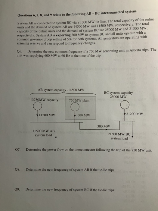
need help to solve this questions about Generator Governor Droop
and Transmission Line. A complete...
Could you please help solve this question. The following generator supplying rated load into a large...
 Could you please help solve this question.
The following generator supplying rated load into a large grid at rated voltage (11kV) and 0.85 PF lagging Generator: 20 MVA, X = j15%. Voltage 11kV i) Determine the internal generator voltage. ii) The load suddenly drops to 50% rated power. If the rotating energy of the generator and its associated turbine is 2.0 p.u-seconds when running at its synchronous speed. It has 2 poles and system frequency is 50 Hz. Determine: (ii-a)...
Could you please help solve this question.
The following generator supplying rated load into a large grid at rated voltage (11kV) and 0.85 PF lagging Generator: 20 MVA, X = j15%. Voltage 11kV i) Determine the internal generator voltage. ii) The load suddenly drops to 50% rated power. If the rotating energy of the generator and its associated turbine is 2.0 p.u-seconds when running at its synchronous speed. It has 2 poles and system frequency is 50 Hz. Determine: (ii-a)...
Question 8: Using a typical frequency response illustrate the different hierarchies of frequency ...
 Question 8: Using a typical frequency response illustrate the different hierarchies of frequency control in large-scale power system. Discuss and illustrate using a numerical example why governors using speed droop or speed regulation cannot alone restore the power system frequency to the pre-disturbance level. Question 9: An isolated 50 Hz synchronous generator is rated at 15 MW which is also the maximum continuous power limit of its prime mover. It is equipped with a speed governor with 5% droop. Initially,...
Question 8: Using a typical frequency response illustrate the different hierarchies of frequency control in large-scale...
 Question 8: Using a typical frequency response illustrate the different hierarchies of frequency control in large-scale power system. Discuss and illustrate using a numerical example why governors using speed droop or speed regulation cannot alone restore the power system frequency to the pre-disturbance level. Question 9: An isolated 50 Hz synchronous generator is rated at 15 MW which is also the maximum continuous power limit of its prime mover. It is equipped with a speed governor with 5% droop. Initially,...
Thank You & Definitely Thumps Up. During a power outage, two generators supply a load with...
 Thank You & Definitely Thumps Up. During a power outage, two generators supply a load with the characteristics depicted in the house diagram below Generator1 Generator 2 Slope 1 MW/Hz 61 Hz 60.5 H2 Slope I MW/Hz 1.5MW .O MW kW P1 1.5 MW 2-10 MW kW (a) If the governor no-load setpoint of Generator 2 is increased to 62 Hz, calculate the load distribution and the new frequency, assuming that the total power supplied does not change? Overlay the...
1. (10 pts) Consider the diagram showing the governor characteristics of two Benerators. Unit 1 is...
 1. (10 pts) Consider the diagram showing the governor characteristics of two Benerators. Unit 1 is rated 1200 MW and Unit 2 is rated 600 MW. They are the only generators in the control area. The base frequency is 60 Hz (a) When the system is operating at 60.00 Hz, what are the respective outputs from Units 1 and 2, and what is the total load in MW? (b) What is the regulation constant R for each generator, in Hz/MW?...
A 5.5 MW variable-speed wind generator with 0.92 power factor is providing power to a grid...
A 5.5 MW variable-speed wind generator with 0.92 power factor is providing power to a grid through a three-phase six pulse bridge converter, a DC link capacitor of 2.2 F, and an inverter. To maintain 60-Hz grid frequency, the required energy storage capacity of the DC link is 1.2 MJ. If the firing-angle of the converter is 45 degrees, calculate the input line current of the converter.
A 1 GW synchronous generator is connected to an infinite bus through a transmission line. The...
A 1 GW synchronous generator is connected to an infinite bus through a transmission line. The infinite bus voltage (per phase) is 100kV (reference voltage), the inductive reactance of the transmission line is 5 ?, the synchronous reactance of the generator is ?? = 8 ?. If the generator delivers its rated power at unity power factor to the infinite bus, compute the following: a) Terminal voltage of the generator (5 Points) b) Equivalent field voltage (5 Points) c) The...
A three-phase, delta-connected, two-pole, synchronous generator is connected to a 60 Hz, 13.5 kV (line-to-line), system....
 A three-phase, delta-connected, two-pole, synchronous generator is connected to a 60 Hz, 13.5 kV (line-to-line), system. The generator is delivering its rated output power, under which conditions pfload = 0.8 lagging and |SI = 20 MVA. The generator per-phase model parameters at rated load are. RA = 0.5 2 Xss = 522 9. What is the generator's line-to-line voltage regulation? Is the voltage regulation positive or negative? 10. If the field current is held at the rated load value, but...
Please, i need a explication step by step of this 1. A 00-Hz short transmission line,...
 Please, i need a explication step by step of this
1. A 00-Hz short transmission line, having R = 0.62 ohms per phase and L = 93.24 millinenrys per phase, supply a three-phase, wye-connected 100 MW load of 0.9 lagging power factor at 215 kV line-to-line voltage. Calculate and determine the following: a. Calculate the sending-end voltage per phase. b. Determine the voltage regulation of the transmission line. c. Determine the efficiency of transmission of the transmission line.
Please, i need a explication step by step of this
1. A 00-Hz short transmission line, having R = 0.62 ohms per phase and L = 93.24 millinenrys per phase, supply a three-phase, wye-connected 100 MW load of 0.9 lagging power factor at 215 kV line-to-line voltage. Calculate and determine the following: a. Calculate the sending-end voltage per phase. b. Determine the voltage regulation of the transmission line. c. Determine the efficiency of transmission of the transmission line.
A three-phase synchronous generator with rated data VM = 20 kV, SM = 100 MVA, n...
A three-phase synchronous generator with rated data VM = 20 kV, SM = 100 MVA, n = 500 rpm is driven by a turbine that can provide a maximum of 1.6 MNm. Synchronous reactance, XS = 3Ω / phase. The armature resistance (Ra ) is neglected. In open circuit mode (P = 0), an excitation current of 300 A is required to obtain rated voltage (VM ). The machine should be phased into a strong grid, 3x20 kV, 50 Hz....
 Could you please help solve this question.
The following generator supplying rated load into a large grid at rated voltage (11kV) and 0.85 PF lagging Generator: 20 MVA, X = j15%. Voltage 11kV i) Determine the internal generator voltage. ii) The load suddenly drops to 50% rated power. If the rotating energy of the generator and its associated turbine is 2.0 p.u-seconds when running at its synchronous speed. It has 2 poles and system frequency is 50 Hz. Determine: (ii-a)...
Could you please help solve this question.
The following generator supplying rated load into a large grid at rated voltage (11kV) and 0.85 PF lagging Generator: 20 MVA, X = j15%. Voltage 11kV i) Determine the internal generator voltage. ii) The load suddenly drops to 50% rated power. If the rotating energy of the generator and its associated turbine is 2.0 p.u-seconds when running at its synchronous speed. It has 2 poles and system frequency is 50 Hz. Determine: (ii-a)...
 Question 8: Using a typical frequency response illustrate the different hierarchies of frequency control in large-scale power system. Discuss and illustrate using a numerical example why governors using speed droop or speed regulation cannot alone restore the power system frequency to the pre-disturbance level. Question 9: An isolated 50 Hz synchronous generator is rated at 15 MW which is also the maximum continuous power limit of its prime mover. It is equipped with a speed governor with 5% droop. Initially,...
 Question 8: Using a typical frequency response illustrate the different hierarchies of frequency control in large-scale power system. Discuss and illustrate using a numerical example why governors using speed droop or speed regulation cannot alone restore the power system frequency to the pre-disturbance level. Question 9: An isolated 50 Hz synchronous generator is rated at 15 MW which is also the maximum continuous power limit of its prime mover. It is equipped with a speed governor with 5% droop. Initially,...
 Thank You & Definitely Thumps Up. During a power outage, two generators supply a load with the characteristics depicted in the house diagram below Generator1 Generator 2 Slope 1 MW/Hz 61 Hz 60.5 H2 Slope I MW/Hz 1.5MW .O MW kW P1 1.5 MW 2-10 MW kW (a) If the governor no-load setpoint of Generator 2 is increased to 62 Hz, calculate the load distribution and the new frequency, assuming that the total power supplied does not change? Overlay the...
 1. (10 pts) Consider the diagram showing the governor characteristics of two Benerators. Unit 1 is rated 1200 MW and Unit 2 is rated 600 MW. They are the only generators in the control area. The base frequency is 60 Hz (a) When the system is operating at 60.00 Hz, what are the respective outputs from Units 1 and 2, and what is the total load in MW? (b) What is the regulation constant R for each generator, in Hz/MW?...
 A three-phase, delta-connected, two-pole, synchronous generator is connected to a 60 Hz, 13.5 kV (line-to-line), system. The generator is delivering its rated output power, under which conditions pfload = 0.8 lagging and |SI = 20 MVA. The generator per-phase model parameters at rated load are. RA = 0.5 2 Xss = 522 9. What is the generator's line-to-line voltage regulation? Is the voltage regulation positive or negative? 10. If the field current is held at the rated load value, but...
 Please, i need a explication step by step of this
1. A 00-Hz short transmission line, having R = 0.62 ohms per phase and L = 93.24 millinenrys per phase, supply a three-phase, wye-connected 100 MW load of 0.9 lagging power factor at 215 kV line-to-line voltage. Calculate and determine the following: a. Calculate the sending-end voltage per phase. b. Determine the voltage regulation of the transmission line. c. Determine the efficiency of transmission of the transmission line.
Please, i need a explication step by step of this
1. A 00-Hz short transmission line, having R = 0.62 ohms per phase and L = 93.24 millinenrys per phase, supply a three-phase, wye-connected 100 MW load of 0.9 lagging power factor at 215 kV line-to-line voltage. Calculate and determine the following: a. Calculate the sending-end voltage per phase. b. Determine the voltage regulation of the transmission line. c. Determine the efficiency of transmission of the transmission line.
Most questions answered within 3 hours.
-
Where is the error in this code sequence?
String s1 = "Hello";
String s2 = "ello";...
asked 10 months ago -
Financial data for Joel de Paris, Inc., for last year
follow:
Joel de Paris, Inc.
Balance...
asked 10 months ago -
Consider this reaction:
Al2(SO4)3 (aq)+ BaCl3
(aq) Al2Cl6 (aq)- +
3BaSO4(s) . What is the...
asked 10 months ago -
Suppose that Savneet is considering increasing her
recent random sample from 20 car rentals to 40...
asked 10 months ago -
Trucks arrive at an unloading terminal at an average rate of 120
per hour.
Trucks arrive...
asked 10 months ago -
Why are methanol and ethanol completely soluble in water while
octanol is not very little soluble....
asked 10 months ago -
A facilities manager at a university reads in a research report
that the mean amount of...
asked 10 months ago -
When the CuSO4 is rehydrated by adding water to the anhydrous
compound, is this an endothermic...
asked 10 months ago -
A ray of sunlight is passing from diamond into crown glass; the
angle of incidence is...
asked 10 months ago -
A block of mass 0.249 kg is placed on top of a light, vertical
spring of...
asked 10 months ago -
how do the kidneys compensate in the presences of acidosis
a) trigger hyperventilate
b) reserve acid...
asked 10 months ago -
Question 501 pts
The rental rate of capital to the firm increases. Which of the
following...
asked 10 months ago