
Homework Answers


Add Answer to:
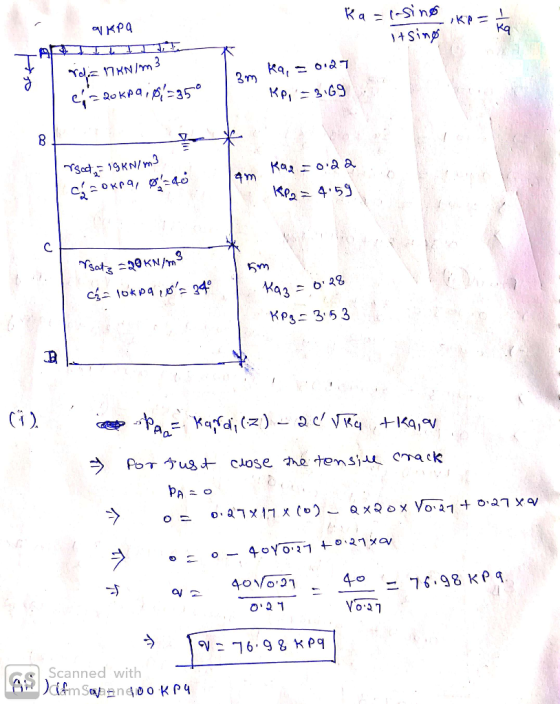
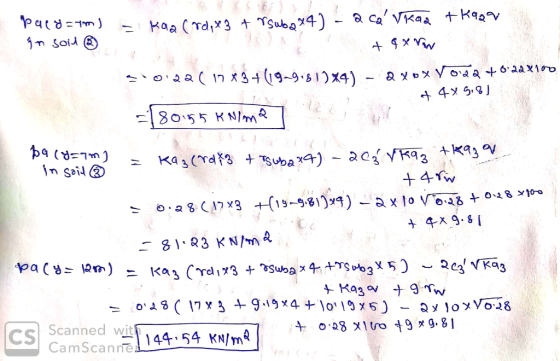
A 12 m high retaining wa is built to retain a 3-layered soil profile shown in...
Question 2 (a) A 4 m high masonry retaining wall of width 1.8 is built to...
 Question 2 (a) A 4 m high masonry retaining wall of width 1.8 is built to retain a 2-layered soil profile shown in Figure 2 on Bonham Road on Hong Kong Island with a surface sucharge of 20 kPa. The soil parameters are given in the figure. During raining season, ground water rises to interface between Soil 1 and Soil 2. Assume that there is no friction between the vertical wall and the soils. The sliding friction angle between the...
A retaining wall with a smooth vertical back has to retain a backfill of cohesionless soil...
 A retaining wall with a smooth vertical back has to retain a backfill of cohesionless soil upto a height f St above ground level. The.coil has a void ratio of 0.83 and the specific gravity of soil solids is 2.68.The water table is located at a depth of 2m below the top of the backfill. The soil above the water table is 20% saturated. The angle of internal friction of the soil above and below water table is 32 and...
7. a) A 10 m high retaining wall supports a fully drained clay soil with a...
 7. a) A 10 m high retaining wall supports a fully drained clay soil with a horizontal surface. The soil properties are: y = 18 kN/m²: =25° and c=4 kN/m2. Sketch the distribution of lateral earth pressure acting on the back of the wall, showing all salient values and the depth of the tension zone. Use Rankine's formula as expressed in familiar symbols below Pa = Kath-2c'tan 45º - (10 marks) (b) Determine the horizontal active thrust on the 7.5...
You have to review the design of a cantilevered concrete retaining wall designed for the height a...
 You have to review the design of a cantilevered concrete retaining wall designed for the height and soil as shown in the figure. Please check the design and provide your recommendation for the following situation: - 200 psf Surcharge load on top of the backfill material Lean clay at foundation same soil for backfill Dry unit weight of soil Cohesion/adhesion of the clay/concrete Bearing capacity of the soil Active earth pressure coefficient Ignore the effect of ground water table Unit...
1. A retaining wall of height 7 m retains soil having an unsurcharged horizontal surface. The...
 1. A retaining wall of height 7 m retains soil having an unsurcharged horizontal surface. The soil properties are c' = 0, Ⓡ' = 32, y = 18 kN/m3 and Ysat= 20 kN/m3. i. ii. Determine the distribution of horizontal stresses on the wall and the magnitude of resultant thrust when water table is at 3 m below the ground surface Determine the magnitude of resultant thrust when the water table is well below the base of the wall Determine...
a) A cantilever retaining wall is constructed to retain the earth in order to create a...
 a) A cantilever retaining wall is constructed to retain the earth in order to create a change of elevation. The stability aspect of a retaining wall is important to prevent any failure of the structure. Referring to Figure 2, check the stability of the cantilever retaining wall against: (i) Sliding (ii) Rotation (ii) Bearing failure (iv) Short conclusion on the stability of the wall [5 marks] [4 marks] [3 marks [2 marks] 0.5 m 4.0 m 0.8 m 1.2 m...
1 Calculate the factor of safety against overturning and sliding for the concrete retaining wall ...
 1 Calculate the factor of safety against overturning and sliding for the concrete retaining wall shown in the figure below, without taking into consideration the passive earth pressure. (50 Points) Assume that 115 lbs/cf unit weight of soil: unit weight of concrete: 150 lbs/cf angle of internal friction: 30 coefficient of friction: 0.350 0° B: 14 5' 2" Ha 14 2.5 Compaction (Soils engineering uses the symbol ys for dry density and uses the term dry unit weight. In the...
3-5 The cross-sectional dimension of a concrete retaining wall is shown in Fig 3-34, together with...
 3-5 The cross-sectional dimension of a concrete retaining wall is shown in Fig 3-34, together with the soil profile of the ground. If a vertical line load (in- cluding the self weight of the wall) acting on the wall foundation is P = 1000 kN/m and its point of application is 3.83 m to the wall front toe A. The horizontal thrust on the wall back is H =350 kN/m and its point of ap- plication is 3.5m above the...
Question 5 (Effective Stress & Consolidation) Figure 05 shows the soil profile of a construction site....
 Question 5 (Effective Stress & Consolidation) Figure 05 shows the soil profile of a construction site. The water table is at the ground surface. Saturated unit weight of the sand is 18.8kN/m' and that of the clay is 19.6kN/m. Assume permeability of the clay is very low and unit weight of water is 10kN/m'. Water Table Sand 5m Clay 6m Figure 05 a) Determine the vertical total stress, pore water pressure, and vertical effective stress at the mid-height of the...
qs=90 1. Assume that the retaining wall in the figure can vield sufficiently. Plot the distribution...
 qs=90
1. Assume that the retaining wall in the figure can vield sufficiently. Plot the distribution of pressure acting on the wall surface, as shown in Figure below. Calculate the total thrust on the wall and determine its point of application. Friction between retaining wall and backfill is neglected. I will be assigned according to the last two digits of the student number. (eng. student number 650170090, will assign a:=90 kPa). q= .... kPa y= 16 EN/m 3 m C=0...
qs=90
1. Assume that the retaining wall in the figure can vield sufficiently. Plot the distribution of pressure acting on the wall surface, as shown in Figure below. Calculate the total thrust on the wall and determine its point of application. Friction between retaining wall and backfill is neglected. I will be assigned according to the last two digits of the student number. (eng. student number 650170090, will assign a:=90 kPa). q= .... kPa y= 16 EN/m 3 m C=0...
 Question 2 (a) A 4 m high masonry retaining wall of width 1.8 is built to retain a 2-layered soil profile shown in Figure 2 on Bonham Road on Hong Kong Island with a surface sucharge of 20 kPa. The soil parameters are given in the figure. During raining season, ground water rises to interface between Soil 1 and Soil 2. Assume that there is no friction between the vertical wall and the soils. The sliding friction angle between the...
 A retaining wall with a smooth vertical back has to retain a backfill of cohesionless soil upto a height f St above ground level. The.coil has a void ratio of 0.83 and the specific gravity of soil solids is 2.68.The water table is located at a depth of 2m below the top of the backfill. The soil above the water table is 20% saturated. The angle of internal friction of the soil above and below water table is 32 and...
 7. a) A 10 m high retaining wall supports a fully drained clay soil with a horizontal surface. The soil properties are: y = 18 kN/m²: =25° and c=4 kN/m2. Sketch the distribution of lateral earth pressure acting on the back of the wall, showing all salient values and the depth of the tension zone. Use Rankine's formula as expressed in familiar symbols below Pa = Kath-2c'tan 45º - (10 marks) (b) Determine the horizontal active thrust on the 7.5...
 You have to review the design of a cantilevered concrete retaining wall designed for the height and soil as shown in the figure. Please check the design and provide your recommendation for the following situation: - 200 psf Surcharge load on top of the backfill material Lean clay at foundation same soil for backfill Dry unit weight of soil Cohesion/adhesion of the clay/concrete Bearing capacity of the soil Active earth pressure coefficient Ignore the effect of ground water table Unit...
 1. A retaining wall of height 7 m retains soil having an unsurcharged horizontal surface. The soil properties are c' = 0, Ⓡ' = 32, y = 18 kN/m3 and Ysat= 20 kN/m3. i. ii. Determine the distribution of horizontal stresses on the wall and the magnitude of resultant thrust when water table is at 3 m below the ground surface Determine the magnitude of resultant thrust when the water table is well below the base of the wall Determine...
 a) A cantilever retaining wall is constructed to retain the earth in order to create a change of elevation. The stability aspect of a retaining wall is important to prevent any failure of the structure. Referring to Figure 2, check the stability of the cantilever retaining wall against: (i) Sliding (ii) Rotation (ii) Bearing failure (iv) Short conclusion on the stability of the wall [5 marks] [4 marks] [3 marks [2 marks] 0.5 m 4.0 m 0.8 m 1.2 m...
 1 Calculate the factor of safety against overturning and sliding for the concrete retaining wall shown in the figure below, without taking into consideration the passive earth pressure. (50 Points) Assume that 115 lbs/cf unit weight of soil: unit weight of concrete: 150 lbs/cf angle of internal friction: 30 coefficient of friction: 0.350 0° B: 14 5' 2" Ha 14 2.5 Compaction (Soils engineering uses the symbol ys for dry density and uses the term dry unit weight. In the...
 3-5 The cross-sectional dimension of a concrete retaining wall is shown in Fig 3-34, together with the soil profile of the ground. If a vertical line load (in- cluding the self weight of the wall) acting on the wall foundation is P = 1000 kN/m and its point of application is 3.83 m to the wall front toe A. The horizontal thrust on the wall back is H =350 kN/m and its point of ap- plication is 3.5m above the...
 Question 5 (Effective Stress & Consolidation) Figure 05 shows the soil profile of a construction site. The water table is at the ground surface. Saturated unit weight of the sand is 18.8kN/m' and that of the clay is 19.6kN/m. Assume permeability of the clay is very low and unit weight of water is 10kN/m'. Water Table Sand 5m Clay 6m Figure 05 a) Determine the vertical total stress, pore water pressure, and vertical effective stress at the mid-height of the...
 qs=90
1. Assume that the retaining wall in the figure can vield sufficiently. Plot the distribution of pressure acting on the wall surface, as shown in Figure below. Calculate the total thrust on the wall and determine its point of application. Friction between retaining wall and backfill is neglected. I will be assigned according to the last two digits of the student number. (eng. student number 650170090, will assign a:=90 kPa). q= .... kPa y= 16 EN/m 3 m C=0...
qs=90
1. Assume that the retaining wall in the figure can vield sufficiently. Plot the distribution of pressure acting on the wall surface, as shown in Figure below. Calculate the total thrust on the wall and determine its point of application. Friction between retaining wall and backfill is neglected. I will be assigned according to the last two digits of the student number. (eng. student number 650170090, will assign a:=90 kPa). q= .... kPa y= 16 EN/m 3 m C=0...
Most questions answered within 3 hours.
-
Where is the error in this code sequence?
String s1 = "Hello";
String s2 = "ello";...
asked 11 months ago -
Financial data for Joel de Paris, Inc., for last year
follow:
Joel de Paris, Inc.
Balance...
asked 11 months ago -
Consider this reaction:
Al2(SO4)3 (aq)+ BaCl3
(aq) Al2Cl6 (aq)- +
3BaSO4(s) . What is the...
asked 11 months ago -
Suppose that Savneet is considering increasing her
recent random sample from 20 car rentals to 40...
asked 11 months ago -
Trucks arrive at an unloading terminal at an average rate of 120
per hour.
Trucks arrive...
asked 11 months ago -
Why are methanol and ethanol completely soluble in water while
octanol is not very little soluble....
asked 11 months ago -
A facilities manager at a university reads in a research report
that the mean amount of...
asked 11 months ago -
When the CuSO4 is rehydrated by adding water to the anhydrous
compound, is this an endothermic...
asked 11 months ago -
A ray of sunlight is passing from diamond into crown glass; the
angle of incidence is...
asked 11 months ago -
A block of mass 0.249 kg is placed on top of a light, vertical
spring of...
asked 11 months ago -
how do the kidneys compensate in the presences of acidosis
a) trigger hyperventilate
b) reserve acid...
asked 11 months ago -
Question 501 pts
The rental rate of capital to the firm increases. Which of the
following...
asked 11 months ago