
Homework Answers

Add Answer to:
Soild Mechanics
Question 2: A beam having the cross-section shown in the drawing is loaded as...
For an extruded beam having the cross section shown, determine: (a) the location of the shear...
 For an extruded beam having the cross section shown, determine: (a) the location of the shear center o (b) the distribution of the shearing stresses caused by a vertical 2.5-kN force V applied at 0. 80-
1.6. A steel cantilever beam having a cross-sectional area of 1.5cm2 is fixed at the left-hand si...
 help plz
1.6. A steel cantilever beam having a cross-sectional area of 1.5cm2 is fixed at the left-hand side and loaded with a 100 N downward vertical force at the extreme end as shown in the figure shown below ba ci (a) Derive the stress equations in Cartesian coordinates if the Airy stress function is φ = aixy + a2xy, The loading conditions are k/2 2 (b) Calculate the stresses and the strains at 8 em from the fixed end...
help plz
1.6. A steel cantilever beam having a cross-sectional area of 1.5cm2 is fixed at the left-hand side and loaded with a 100 N downward vertical force at the extreme end as shown in the figure shown below ba ci (a) Derive the stress equations in Cartesian coordinates if the Airy stress function is φ = aixy + a2xy, The loading conditions are k/2 2 (b) Calculate the stresses and the strains at 8 em from the fixed end...
A rectangular cross section at a location along a beam in bending is
 (a). A rectangular cross section at a location along a beam in bending is acted upon by a bending moment and a shear force. The cross section is \(120 \mathrm{~mm}\) wide, \(300 \mathrm{~mm}\) deep and is orientated such that it is in bending about its major axis of bending. The magnitudes of the bending moment and shear force are \(315 \mathrm{kNm}\) and \(240 \mathrm{kN}\) respectively. Determine the maximum bending and shear stresses on the cross section. Plot the bending and...
3. Two vertical forces are applied to a beam of the cross section as shown in...
 3. Two vertical forces are applied to a beam of the cross section as shown in Figure 3 Determine the maximum tensile and compressive stresses in portion BC of the beam 20 marks) (CLO3:PLO3:C4) 75 65 kN 65 kN A B 50 mm 50 mm Figure 3
A beam is loaded by a shear force V. The beam cross-section is shown below. The...
 A beam is loaded by a shear force V. The beam cross-section is
shown below. The moment of inertia of the cross-section is 347.1
in4. The centroid of the cross-section is 6.25 inches
from the base. Determine:
a) the shear stress at point A.
b) the shear stress at point B.
c) the maximum shear stress in the cross-section.
V = 50 (kips)
The maximum shear stress at point A is _____(ksi)
The maximum shear stress at point B is...
A beam is loaded by a shear force V. The beam cross-section is
shown below. The moment of inertia of the cross-section is 347.1
in4. The centroid of the cross-section is 6.25 inches
from the base. Determine:
a) the shear stress at point A.
b) the shear stress at point B.
c) the maximum shear stress in the cross-section.
V = 50 (kips)
The maximum shear stress at point A is _____(ksi)
The maximum shear stress at point B is...
I-beam loaded as a cantilever beam 2. An I-beam is loaded as a cantilever beam as shown below. The cross-section of the...
 I-beam loaded as a cantilever beam
2. An I-beam is loaded as a cantilever beam as shown below. The cross-section of the beam is also shown. Indicate on both illustrations, by circling and labeling, the location of the maximum tensile stress and the maximum compressive stress.
2. An I-beam is loaded as a cantilever beam as shown below. The cross-section of the beam is also shown. Indicate on both illustrations, by circling and labeling, the location of the maximum tensile...
I-beam loaded as a cantilever beam
2. An I-beam is loaded as a cantilever beam as shown below. The cross-section of the beam is also shown. Indicate on both illustrations, by circling and labeling, the location of the maximum tensile stress and the maximum compressive stress.
2. An I-beam is loaded as a cantilever beam as shown below. The cross-section of the beam is also shown. Indicate on both illustrations, by circling and labeling, the location of the maximum tensile...
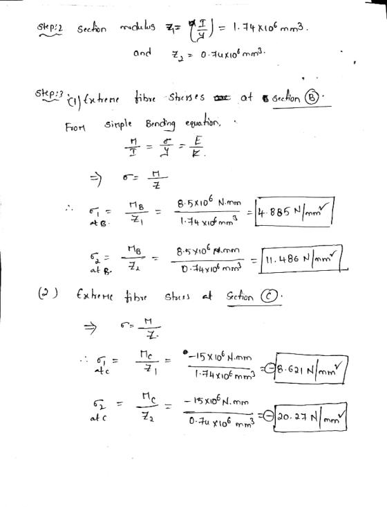
A beam having a T-Section is loaded as shown in figure below.
 A beam having a T-Section is loaded as shown in figure below. a. Draw the Shear Force & Bending Moment Diagram b. Locate the Nuetral Axis c. Find the maximum tensile and compressive bending stress d. Find the maximum shear stress e Find the Bending Stress and Shear Stress at the points marked on the cross section
A rectangular beam is subjected to the loadings shown in Figure Q.16(a) has cross section of...
 A rectangular beam is subjected to the loadings shown in Figure Q.16(a) has cross section of 100 mm x 300 mm as shown in Figure Q.16(b). An axial load of 5 kN is applied along the centroid of the cross-section at one end of the beam. Compute the normal stress and shear stress at point P through the cut-section of P in the beam. [15 marks] у 10 kN/m P Ž 5 KN --- 00 P k 3 m -...
Problem 1 For the loaded beam with the cross-section shown: A. Find the location of the neutral a...
 Problem 1 For the loaded beam with the cross-section shown: A. Find the location of the neutral axis B. Compute the moment of inertia of the section around the neutral axis C. Locate the section of maximum moment then compute the maximum stress due to bending, fb D. Locate the section of maximum shear-compute the shear stress at the neutral axis 3.0 k 8" 1.5 k/ft 1.0 k/ft 2" 8 10 ft 6 ft 4 ft 2" Cross-Section
Problem 1...
Problem 1 For the loaded beam with the cross-section shown: A. Find the location of the neutral axis B. Compute the moment of inertia of the section around the neutral axis C. Locate the section of maximum moment then compute the maximum stress due to bending, fb D. Locate the section of maximum shear-compute the shear stress at the neutral axis 3.0 k 8" 1.5 k/ft 1.0 k/ft 2" 8 10 ft 6 ft 4 ft 2" Cross-Section
Problem 1...
Two vertical forces are applied to a beam of the cross section shown in fig 2....
 Two vertical forces are applied to a beam of the cross section shown in fig 2. Determine the maximum tensile and compressive stresses in portion BC of the beam. 10 mm 10 mm 1o kN 50 mm 250 mm- 10 150 mm 150 mm 50 mm
 For an extruded beam having the cross section shown, determine: (a) the location of the shear center o (b) the distribution of the shearing stresses caused by a vertical 2.5-kN force V applied at 0. 80-
 help plz
1.6. A steel cantilever beam having a cross-sectional area of 1.5cm2 is fixed at the left-hand side and loaded with a 100 N downward vertical force at the extreme end as shown in the figure shown below ba ci (a) Derive the stress equations in Cartesian coordinates if the Airy stress function is φ = aixy + a2xy, The loading conditions are k/2 2 (b) Calculate the stresses and the strains at 8 em from the fixed end...
help plz
1.6. A steel cantilever beam having a cross-sectional area of 1.5cm2 is fixed at the left-hand side and loaded with a 100 N downward vertical force at the extreme end as shown in the figure shown below ba ci (a) Derive the stress equations in Cartesian coordinates if the Airy stress function is φ = aixy + a2xy, The loading conditions are k/2 2 (b) Calculate the stresses and the strains at 8 em from the fixed end...
 3. Two vertical forces are applied to a beam of the cross section as shown in Figure 3 Determine the maximum tensile and compressive stresses in portion BC of the beam 20 marks) (CLO3:PLO3:C4) 75 65 kN 65 kN A B 50 mm 50 mm Figure 3
 A beam is loaded by a shear force V. The beam cross-section is
shown below. The moment of inertia of the cross-section is 347.1
in4. The centroid of the cross-section is 6.25 inches
from the base. Determine:
a) the shear stress at point A.
b) the shear stress at point B.
c) the maximum shear stress in the cross-section.
V = 50 (kips)
The maximum shear stress at point A is _____(ksi)
The maximum shear stress at point B is...
A beam is loaded by a shear force V. The beam cross-section is
shown below. The moment of inertia of the cross-section is 347.1
in4. The centroid of the cross-section is 6.25 inches
from the base. Determine:
a) the shear stress at point A.
b) the shear stress at point B.
c) the maximum shear stress in the cross-section.
V = 50 (kips)
The maximum shear stress at point A is _____(ksi)
The maximum shear stress at point B is...
 I-beam loaded as a cantilever beam
2. An I-beam is loaded as a cantilever beam as shown below. The cross-section of the beam is also shown. Indicate on both illustrations, by circling and labeling, the location of the maximum tensile stress and the maximum compressive stress.
2. An I-beam is loaded as a cantilever beam as shown below. The cross-section of the beam is also shown. Indicate on both illustrations, by circling and labeling, the location of the maximum tensile...
I-beam loaded as a cantilever beam
2. An I-beam is loaded as a cantilever beam as shown below. The cross-section of the beam is also shown. Indicate on both illustrations, by circling and labeling, the location of the maximum tensile stress and the maximum compressive stress.
2. An I-beam is loaded as a cantilever beam as shown below. The cross-section of the beam is also shown. Indicate on both illustrations, by circling and labeling, the location of the maximum tensile...
 A rectangular beam is subjected to the loadings shown in Figure Q.16(a) has cross section of 100 mm x 300 mm as shown in Figure Q.16(b). An axial load of 5 kN is applied along the centroid of the cross-section at one end of the beam. Compute the normal stress and shear stress at point P through the cut-section of P in the beam. [15 marks] у 10 kN/m P Ž 5 KN --- 00 P k 3 m -...
 Problem 1 For the loaded beam with the cross-section shown: A. Find the location of the neutral axis B. Compute the moment of inertia of the section around the neutral axis C. Locate the section of maximum moment then compute the maximum stress due to bending, fb D. Locate the section of maximum shear-compute the shear stress at the neutral axis 3.0 k 8" 1.5 k/ft 1.0 k/ft 2" 8 10 ft 6 ft 4 ft 2" Cross-Section
Problem 1...
Problem 1 For the loaded beam with the cross-section shown: A. Find the location of the neutral axis B. Compute the moment of inertia of the section around the neutral axis C. Locate the section of maximum moment then compute the maximum stress due to bending, fb D. Locate the section of maximum shear-compute the shear stress at the neutral axis 3.0 k 8" 1.5 k/ft 1.0 k/ft 2" 8 10 ft 6 ft 4 ft 2" Cross-Section
Problem 1...
 Two vertical forces are applied to a beam of the cross section shown in fig 2. Determine the maximum tensile and compressive stresses in portion BC of the beam. 10 mm 10 mm 1o kN 50 mm 250 mm- 10 150 mm 150 mm 50 mm
Most questions answered within 3 hours.
-
Where is the error in this code sequence?
String s1 = "Hello";
String s2 = "ello";...
asked 10 months ago -
Financial data for Joel de Paris, Inc., for last year
follow:
Joel de Paris, Inc.
Balance...
asked 10 months ago -
Consider this reaction:
Al2(SO4)3 (aq)+ BaCl3
(aq) Al2Cl6 (aq)- +
3BaSO4(s) . What is the...
asked 10 months ago -
Suppose that Savneet is considering increasing her
recent random sample from 20 car rentals to 40...
asked 10 months ago -
Trucks arrive at an unloading terminal at an average rate of 120
per hour.
Trucks arrive...
asked 10 months ago -
Why are methanol and ethanol completely soluble in water while
octanol is not very little soluble....
asked 10 months ago -
A facilities manager at a university reads in a research report
that the mean amount of...
asked 10 months ago -
When the CuSO4 is rehydrated by adding water to the anhydrous
compound, is this an endothermic...
asked 10 months ago -
A ray of sunlight is passing from diamond into crown glass; the
angle of incidence is...
asked 10 months ago -
A block of mass 0.249 kg is placed on top of a light, vertical
spring of...
asked 10 months ago -
how do the kidneys compensate in the presences of acidosis
a) trigger hyperventilate
b) reserve acid...
asked 10 months ago -
Question 501 pts
The rental rate of capital to the firm increases. Which of the
following...
asked 10 months ago