


Homework Answers

Add Answer to:
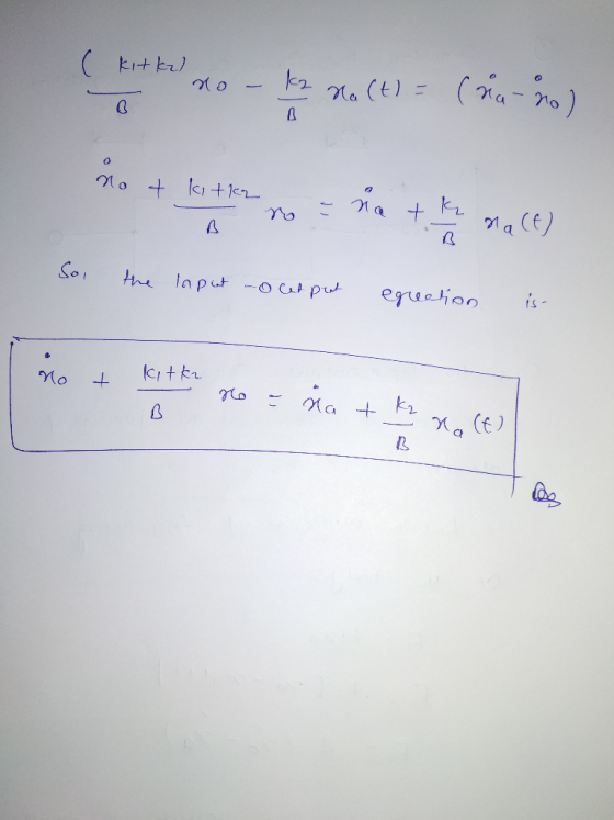
For the mechanical system shown below find the input-output equation relating xolt) to the displacement input...
Problem B-4-1 Find the transfer function X (s)/X/(s) of the mechanical system shown in Figure 4-50....
 Problem B-4-1 Find the transfer function X (s)/X/(s) of the mechanical system shown in Figure 4-50. The displacements x; and X, are measured from their respective equilibrium positions. Obtain the displacement xo(t) when the input x;(t) is a step displacement of magnitude X; occurring at t = 0. Assume that x.(0-) = 0. T Figure 4-50 Mechanical system.
7. Consider the mechanical system shown below. The system initially at rest. The displacements u, y,...
 7. Consider the mechanical system shown below. The system initially at rest. The displacements u, y, and z are measured from their respective rest positions. Given that u is the input, y is the output, 1) Obtain the transfer function of the system (20pt). 2) Obtain a state-space representation of the system (20pt). I b, - obteranlara k, 12 WI
Find transfer function given input force and input displacement
Consider the mechanical system shown in Figure 4-55. The system is at rest for t<0. The input force "u" is given at t=0. The displacement "x" is the output of thesystem and is measured from the equilibrium position. Obtain the transfer function X(s)/U(s) for "u" as a force AND for "u" as a displacement for the end of the node.
Consider the mechanical system shown in Figure. Displacements Xi and Xo are measured from their respective...
 Consider the mechanical system shown in Figure. Displacements Xi and Xo are measured from their respective equilibrium positions. Derive the transfer function of the system wherein Xi is the input and Xo is the output. Then obtain the response Xo (t) ki bi b,* when input Xi (t) is a step displacement of magnitude Xi occurring at t 0. Assume that Xo (0-) 0.
6. Consider the liquid-level system shown. Assume that the outflow rate Q(m/s) through the outflow valve...
 6. Consider the liquid-level system shown. Assume that the outflow rate Q(m/s) through the outflow valve is related to the head H by: Q=kVH = 0.01VH Also assume when the inflow rate Qi is 0.015m3/s the head is constant. At t=0 the inflow valve is closed, so there is no flow for t0. Find the time necessary to empty the tank to half the original head. The area of the tank is 2m2 TIL Capacitance c
A vibration isolation system for a 1-DOF mechanical system is shown below. Displacement of the mass...
 A vibration isolation system for a 1-DOF mechanical system is shown below. Displacement of the mass x is measured from the static equilibrium position and the system parameters are m = 0.3 kg. k=10N/m, b = 4.4 Ns/m, and by = 0.5 Ns/m. Fixed 1. TI W Fixed base Figure / sehen voulon tem a) Derive the mathematical model of the system. Make sure you have the FBD and all equations and signs are properly showcased. b) Use the system...
Q-5 Obtain the transfer functions Xi(s)/U(s) and Xa(s)/U(s) of the mechanical system shown below....
 Q-5 Obtain the transfer functions Xi(s)/U(s) and Xa(s)/U(s) of the mechanical system shown below. (35p) Lu x2 m2 bi
Q-5 Obtain the transfer functions Xi(s)/U(s) and Xa(s)/U(s) of the mechanical system shown below. (35p) Lu x2 m2 bi
Q-5 Obtain the transfer functions Xi(s)/U(s) and Xa(s)/U(s) of the mechanical system shown below. (35p) Lu x2 m2 bi
For the system shown in Fig. 1, solve the following problems. (a) Find the transfer function, G(s...
 For the system shown in Fig. 1, solve the following problems. (a) Find the transfer function, G(s)X2 (s)/F(s) (b) Does the system oscillate with a unit step input (f (t))? Explain the reason (c) Decide if the system(x2 (t)) is stable with a unit step input (f (t))? Explain the reason 1. 320) 8 kg 2 N/m 4N-s/m 2N-s/m Fig. 1 2. There are two suspensions for a car as shown in Fig. 2 (a) Find the equations of each...
Find the transfer function (X1/F) for the mechanical system shown below
 Find the transfer function (X/F) for the mechanical system shown below
Question 1 Figure Q1 shows a mechanical system. The system input is T) and output is supposed to ...
 Please write down the steps by steps solution, thank
you!
Question 1 Figure Q1 shows a mechanical system. The system input is T) and output is supposed to be 0. Please find the transfer function from T to θ 3, and discuss the stability of the system if the input is a unit impulse signal. (30 marks) To 01(t) 01t) I kg-m2 N 10 030) N2 100 100 kg-m2 100 N-m/rad 100 N-m-s/rad Figure Q1
Question 1 Figure Q1 shows...
Please write down the steps by steps solution, thank
you!
Question 1 Figure Q1 shows a mechanical system. The system input is T) and output is supposed to be 0. Please find the transfer function from T to θ 3, and discuss the stability of the system if the input is a unit impulse signal. (30 marks) To 01(t) 01t) I kg-m2 N 10 030) N2 100 100 kg-m2 100 N-m/rad 100 N-m-s/rad Figure Q1
Question 1 Figure Q1 shows...
 Problem B-4-1 Find the transfer function X (s)/X/(s) of the mechanical system shown in Figure 4-50. The displacements x; and X, are measured from their respective equilibrium positions. Obtain the displacement xo(t) when the input x;(t) is a step displacement of magnitude X; occurring at t = 0. Assume that x.(0-) = 0. T Figure 4-50 Mechanical system.
 7. Consider the mechanical system shown below. The system initially at rest. The displacements u, y, and z are measured from their respective rest positions. Given that u is the input, y is the output, 1) Obtain the transfer function of the system (20pt). 2) Obtain a state-space representation of the system (20pt). I b, - obteranlara k, 12 WI
 Consider the mechanical system shown in Figure. Displacements Xi and Xo are measured from their respective equilibrium positions. Derive the transfer function of the system wherein Xi is the input and Xo is the output. Then obtain the response Xo (t) ki bi b,* when input Xi (t) is a step displacement of magnitude Xi occurring at t 0. Assume that Xo (0-) 0.
 6. Consider the liquid-level system shown. Assume that the outflow rate Q(m/s) through the outflow valve is related to the head H by: Q=kVH = 0.01VH Also assume when the inflow rate Qi is 0.015m3/s the head is constant. At t=0 the inflow valve is closed, so there is no flow for t0. Find the time necessary to empty the tank to half the original head. The area of the tank is 2m2 TIL Capacitance c
 A vibration isolation system for a 1-DOF mechanical system is shown below. Displacement of the mass x is measured from the static equilibrium position and the system parameters are m = 0.3 kg. k=10N/m, b = 4.4 Ns/m, and by = 0.5 Ns/m. Fixed 1. TI W Fixed base Figure / sehen voulon tem a) Derive the mathematical model of the system. Make sure you have the FBD and all equations and signs are properly showcased. b) Use the system...
 Q-5 Obtain the transfer functions Xi(s)/U(s) and Xa(s)/U(s) of the mechanical system shown below. (35p) Lu x2 m2 bi
Q-5 Obtain the transfer functions Xi(s)/U(s) and Xa(s)/U(s) of the mechanical system shown below. (35p) Lu x2 m2 bi
Q-5 Obtain the transfer functions Xi(s)/U(s) and Xa(s)/U(s) of the mechanical system shown below. (35p) Lu x2 m2 bi
 For the system shown in Fig. 1, solve the following problems. (a) Find the transfer function, G(s)X2 (s)/F(s) (b) Does the system oscillate with a unit step input (f (t))? Explain the reason (c) Decide if the system(x2 (t)) is stable with a unit step input (f (t))? Explain the reason 1. 320) 8 kg 2 N/m 4N-s/m 2N-s/m Fig. 1 2. There are two suspensions for a car as shown in Fig. 2 (a) Find the equations of each...
 Please write down the steps by steps solution, thank
you!
Question 1 Figure Q1 shows a mechanical system. The system input is T) and output is supposed to be 0. Please find the transfer function from T to θ 3, and discuss the stability of the system if the input is a unit impulse signal. (30 marks) To 01(t) 01t) I kg-m2 N 10 030) N2 100 100 kg-m2 100 N-m/rad 100 N-m-s/rad Figure Q1
Question 1 Figure Q1 shows...
Please write down the steps by steps solution, thank
you!
Question 1 Figure Q1 shows a mechanical system. The system input is T) and output is supposed to be 0. Please find the transfer function from T to θ 3, and discuss the stability of the system if the input is a unit impulse signal. (30 marks) To 01(t) 01t) I kg-m2 N 10 030) N2 100 100 kg-m2 100 N-m/rad 100 N-m-s/rad Figure Q1
Question 1 Figure Q1 shows...
Most questions answered within 3 hours.
-
Where is the error in this code sequence?
String s1 = "Hello";
String s2 = "ello";...
asked 10 months ago -
Financial data for Joel de Paris, Inc., for last year
follow:
Joel de Paris, Inc.
Balance...
asked 10 months ago -
Consider this reaction:
Al2(SO4)3 (aq)+ BaCl3
(aq) Al2Cl6 (aq)- +
3BaSO4(s) . What is the...
asked 10 months ago -
Suppose that Savneet is considering increasing her
recent random sample from 20 car rentals to 40...
asked 10 months ago -
Trucks arrive at an unloading terminal at an average rate of 120
per hour.
Trucks arrive...
asked 10 months ago -
Why are methanol and ethanol completely soluble in water while
octanol is not very little soluble....
asked 10 months ago -
A facilities manager at a university reads in a research report
that the mean amount of...
asked 10 months ago -
When the CuSO4 is rehydrated by adding water to the anhydrous
compound, is this an endothermic...
asked 10 months ago -
A ray of sunlight is passing from diamond into crown glass; the
angle of incidence is...
asked 10 months ago -
A block of mass 0.249 kg is placed on top of a light, vertical
spring of...
asked 10 months ago -
how do the kidneys compensate in the presences of acidosis
a) trigger hyperventilate
b) reserve acid...
asked 10 months ago -
Question 501 pts
The rental rate of capital to the firm increases. Which of the
following...
asked 10 months ago