
Homework Answers


Add Answer to:
What's the Gain of this circuit?
Circuit 2: cs RS RF 10K 0.1u 10k 1 KHz,...
Solve this circuit? Rf 10k О-15 R1 1k V. Vo ua741 15 Figura 5-3 Amplificador inversor...
 Solve this circuit?
Rf 10k О-15 R1 1k V. Vo ua741 15 Figura 5-3 Amplificador inversor para la práctica
Solve this circuit?
Rf 10k О-15 R1 1k V. Vo ua741 15 Figura 5-3 Amplificador inversor para la práctica
RS Given that R2-40K, R5-10K, R6-10K, R7-10K, RL 5K, C 1-1 000uF, C3-. 1 uF, C4-1 000uF, C2-0pF and Vec=1 5V. Vcc C3 n RT Vin C1 vo Draw the DC model of this circuit. a. R6 RL Find the bias volta...
 RS Given that R2-40K, R5-10K, R6-10K, R7-10K, RL 5K, C 1-1 000uF, C3-. 1 uF, C4-1 000uF, C2-0pF and Vec=1 5V. Vcc C3 n RT Vin C1 vo Draw the DC model of this circuit. a. R6 RL Find the bias voltage at pin 3 of the op amp. b. ua741 R2 C4 Find the low-frequency cut-off of this circuit. c. acts like a short circuit? What is the input current at pin 2 of the op amp? e. f....
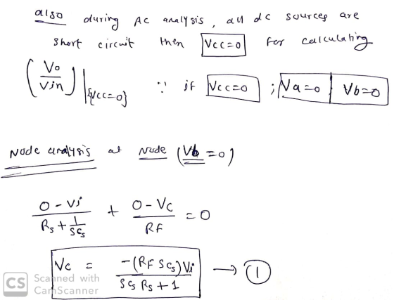
3) Find the output voltage for the circuit shown below. Rf 10K +12V DC R1 Vaw...
 3) Find the output voltage for the circuit shown below. Rf 10K +12V DC R1 Vaw 2.2K IC1 UA741 Vb R2 W 2.2K -12V DC R3 Z RL 10K Fig 1 Differential amplifier using one opamp
C- Amplifier: Consider figure 3. This circuit uses the JFET to amplify the input signal voltage F...
 C- Amplifier: Consider figure 3. This circuit uses the JFET to amplify the input signal voltage First the dc operation must be set. Use equation 1 and your previous data to calculate the value of Vas required to give I-0.5 mA. Determine the source resistance Rs needed to set this bias. Set up the circuit of figure 3 with your calculated value of Rs. Measure Vo and Vs to determine if your operating conditions are correct. Apply an input voltage...
Design the CS amplifier in Fig. L7.17(a) to achieve a small-signal gain of at least 4,--5 V/V. Us...
 Design the CS amplifier in Fig. L7.17(a) to achieve a small-signal gain of at least 4,--5 V/V. Use supplies of V+--K = 15 V, Rsig-50 Ω, RL-10 kQ, and R1R2 = 10 kQ, and design the circuit to have ID-1 mA and a DC voltage at the gate Vo = 0 V. Use Cc,-CC2-CS-47 μF. What is the expected DC voltage at the source of the NMOS? C1 sig V. Rs sig
Design the CS amplifier in Fig. L7.17(a) to...
Design the CS amplifier in Fig. L7.17(a) to achieve a small-signal gain of at least 4,--5 V/V. Use supplies of V+--K = 15 V, Rsig-50 Ω, RL-10 kQ, and R1R2 = 10 kQ, and design the circuit to have ID-1 mA and a DC voltage at the gate Vo = 0 V. Use Cc,-CC2-CS-47 μF. What is the expected DC voltage at the source of the NMOS? C1 sig V. Rs sig
Design the CS amplifier in Fig. L7.17(a) to...
1. Find the operating point of the circuit below assuming the op amp is ideal 2. Estimate the midband voltage gain Avs-...
 1. Find the operating point of the circuit below assuming the op amp is ideal 2. Estimate the midband voltage gain Avs-vo v, 3. Choose values for C1 and C2 so that the pole frequency associated with Ci is 1 Hz and the pole frequency associated with C is 400 Hz. 4. At what frequency fz does a zero occur? 6. Why does the amplifier's gain drop at high frequencies? C2 R1 R2 99K C2] 2K param C2 0.1uF U1...
. Consider the circuit below. If Vs-Vincos(ot), show that 2 =-1+ jc0C, R, . Plot Vo, as in function of ω for 0<ω< 10 rad/s if Rs-1kQ, Rf-10 kQ, and CF-0.1 mF. What does this circuit do? CF Rf V...
 . Consider the circuit below. If Vs-Vincos(ot), show that 2 =-1+ jc0C, R, . Plot Vo, as in function of ω for 0<ω< 10 rad/s if Rs-1kQ, Rf-10 kQ, and CF-0.1 mF. What does this circuit do? CF Rf Vo Rs This is an example of an ACTIVE FILTER because this circuit can amplify as well as filter an input signal.
. Consider the circuit below. If Vs-Vincos(ot), show that 2 =-1+ jc0C, R, . Plot Vo, as in function...
. Consider the circuit below. If Vs-Vincos(ot), show that 2 =-1+ jc0C, R, . Plot Vo, as in function of ω for 0<ω< 10 rad/s if Rs-1kQ, Rf-10 kQ, and CF-0.1 mF. What does this circuit do? CF Rf Vo Rs This is an example of an ACTIVE FILTER because this circuit can amplify as well as filter an input signal.
. Consider the circuit below. If Vs-Vincos(ot), show that 2 =-1+ jc0C, R, . Plot Vo, as in function...
1. Can you help me convert this circuit into a small - signal equivalent circuit? 2. Can you tell me how to calculate R...
 1. Can you help me convert this circuit into a small - signal
equivalent circuit?
2. Can you tell me how to calculate Rin and Rout directly in
that circuit?
3. Also I wanna know about values of Rin, Rout, VGD(voltage
between gate-drain), Av(entire voltage gain)
스를 잡도록 하였다. 또한, M3와 R1으로 전류원을 구성하여 능동 부하 M2의 바이어 해서 입력 바이어 스를 잡도록 하였다. FDC6322CP FDC6322CP V1 M3 M2 5Vdc V4 C2 5Vdc R1 30 1u R4 10k R3 10k...
1. Can you help me convert this circuit into a small - signal
equivalent circuit?
2. Can you tell me how to calculate Rin and Rout directly in
that circuit?
3. Also I wanna know about values of Rin, Rout, VGD(voltage
between gate-drain), Av(entire voltage gain)
스를 잡도록 하였다. 또한, M3와 R1으로 전류원을 구성하여 능동 부하 M2의 바이어 해서 입력 바이어 스를 잡도록 하였다. FDC6322CP FDC6322CP V1 M3 M2 5Vdc V4 C2 5Vdc R1 30 1u R4 10k R3 10k...
Q2. For the op-amp circuit as shown below, given that RS = 49.5 k, RL =...
 Q2. For the op-amp circuit as shown below, given that RS = 49.5 k, RL = 12 k 2, R1 = 10 kO, R2 = 9 ㏀, R3 = 7.5 ko, R4 = 5 ㏀R5 = 2.2 k2 Ry vo Ry Ri Rs (a) Determine the voltage gain G1-vo1/vs: Submit Answer Tries o/5 (b) Determine the voltage gain G2-vo/vs: Submit Answer Tries o/5 Q3. For the op-amp circuit shown below, find the value of VO, where R1 = 20 Ω,...
I need help to measure the high frequency cutoff. The circuit below is for HIGH PASS...
 I need help to measure the high frequency cutoff. The circuit
below is for HIGH PASS FILTER
I made it but I dont know how to accurately measure the high
cutoff as what we did in the lab. in the lab we get 14.35
kHz but when I try in the multisim and varing the freqency
as shown in the table below I dont get any change.
Please do it in multisim and explain your answer, thanks.
f
1-kHz
2-kHz...
I need help to measure the high frequency cutoff. The circuit
below is for HIGH PASS FILTER
I made it but I dont know how to accurately measure the high
cutoff as what we did in the lab. in the lab we get 14.35
kHz but when I try in the multisim and varing the freqency
as shown in the table below I dont get any change.
Please do it in multisim and explain your answer, thanks.
f
1-kHz
2-kHz...
 Solve this circuit?
Rf 10k О-15 R1 1k V. Vo ua741 15 Figura 5-3 Amplificador inversor para la práctica
Solve this circuit?
Rf 10k О-15 R1 1k V. Vo ua741 15 Figura 5-3 Amplificador inversor para la práctica
 RS Given that R2-40K, R5-10K, R6-10K, R7-10K, RL 5K, C 1-1 000uF, C3-. 1 uF, C4-1 000uF, C2-0pF and Vec=1 5V. Vcc C3 n RT Vin C1 vo Draw the DC model of this circuit. a. R6 RL Find the bias voltage at pin 3 of the op amp. b. ua741 R2 C4 Find the low-frequency cut-off of this circuit. c. acts like a short circuit? What is the input current at pin 2 of the op amp? e. f....
 3) Find the output voltage for the circuit shown below. Rf 10K +12V DC R1 Vaw 2.2K IC1 UA741 Vb R2 W 2.2K -12V DC R3 Z RL 10K Fig 1 Differential amplifier using one opamp
 C- Amplifier: Consider figure 3. This circuit uses the JFET to amplify the input signal voltage First the dc operation must be set. Use equation 1 and your previous data to calculate the value of Vas required to give I-0.5 mA. Determine the source resistance Rs needed to set this bias. Set up the circuit of figure 3 with your calculated value of Rs. Measure Vo and Vs to determine if your operating conditions are correct. Apply an input voltage...
 Design the CS amplifier in Fig. L7.17(a) to achieve a small-signal gain of at least 4,--5 V/V. Use supplies of V+--K = 15 V, Rsig-50 Ω, RL-10 kQ, and R1R2 = 10 kQ, and design the circuit to have ID-1 mA and a DC voltage at the gate Vo = 0 V. Use Cc,-CC2-CS-47 μF. What is the expected DC voltage at the source of the NMOS? C1 sig V. Rs sig
Design the CS amplifier in Fig. L7.17(a) to...
Design the CS amplifier in Fig. L7.17(a) to achieve a small-signal gain of at least 4,--5 V/V. Use supplies of V+--K = 15 V, Rsig-50 Ω, RL-10 kQ, and R1R2 = 10 kQ, and design the circuit to have ID-1 mA and a DC voltage at the gate Vo = 0 V. Use Cc,-CC2-CS-47 μF. What is the expected DC voltage at the source of the NMOS? C1 sig V. Rs sig
Design the CS amplifier in Fig. L7.17(a) to...
 1. Find the operating point of the circuit below assuming the op amp is ideal 2. Estimate the midband voltage gain Avs-vo v, 3. Choose values for C1 and C2 so that the pole frequency associated with Ci is 1 Hz and the pole frequency associated with C is 400 Hz. 4. At what frequency fz does a zero occur? 6. Why does the amplifier's gain drop at high frequencies? C2 R1 R2 99K C2] 2K param C2 0.1uF U1...
 . Consider the circuit below. If Vs-Vincos(ot), show that 2 =-1+ jc0C, R, . Plot Vo, as in function of ω for 0<ω< 10 rad/s if Rs-1kQ, Rf-10 kQ, and CF-0.1 mF. What does this circuit do? CF Rf Vo Rs This is an example of an ACTIVE FILTER because this circuit can amplify as well as filter an input signal.
. Consider the circuit below. If Vs-Vincos(ot), show that 2 =-1+ jc0C, R, . Plot Vo, as in function...
. Consider the circuit below. If Vs-Vincos(ot), show that 2 =-1+ jc0C, R, . Plot Vo, as in function of ω for 0<ω< 10 rad/s if Rs-1kQ, Rf-10 kQ, and CF-0.1 mF. What does this circuit do? CF Rf Vo Rs This is an example of an ACTIVE FILTER because this circuit can amplify as well as filter an input signal.
. Consider the circuit below. If Vs-Vincos(ot), show that 2 =-1+ jc0C, R, . Plot Vo, as in function...
 1. Can you help me convert this circuit into a small - signal
equivalent circuit?
2. Can you tell me how to calculate Rin and Rout directly in
that circuit?
3. Also I wanna know about values of Rin, Rout, VGD(voltage
between gate-drain), Av(entire voltage gain)
스를 잡도록 하였다. 또한, M3와 R1으로 전류원을 구성하여 능동 부하 M2의 바이어 해서 입력 바이어 스를 잡도록 하였다. FDC6322CP FDC6322CP V1 M3 M2 5Vdc V4 C2 5Vdc R1 30 1u R4 10k R3 10k...
1. Can you help me convert this circuit into a small - signal
equivalent circuit?
2. Can you tell me how to calculate Rin and Rout directly in
that circuit?
3. Also I wanna know about values of Rin, Rout, VGD(voltage
between gate-drain), Av(entire voltage gain)
스를 잡도록 하였다. 또한, M3와 R1으로 전류원을 구성하여 능동 부하 M2의 바이어 해서 입력 바이어 스를 잡도록 하였다. FDC6322CP FDC6322CP V1 M3 M2 5Vdc V4 C2 5Vdc R1 30 1u R4 10k R3 10k...
 Q2. For the op-amp circuit as shown below, given that RS = 49.5 k, RL = 12 k 2, R1 = 10 kO, R2 = 9 ㏀, R3 = 7.5 ko, R4 = 5 ㏀R5 = 2.2 k2 Ry vo Ry Ri Rs (a) Determine the voltage gain G1-vo1/vs: Submit Answer Tries o/5 (b) Determine the voltage gain G2-vo/vs: Submit Answer Tries o/5 Q3. For the op-amp circuit shown below, find the value of VO, where R1 = 20 Ω,...
 I need help to measure the high frequency cutoff. The circuit
below is for HIGH PASS FILTER
I made it but I dont know how to accurately measure the high
cutoff as what we did in the lab. in the lab we get 14.35
kHz but when I try in the multisim and varing the freqency
as shown in the table below I dont get any change.
Please do it in multisim and explain your answer, thanks.
f
1-kHz
2-kHz...
I need help to measure the high frequency cutoff. The circuit
below is for HIGH PASS FILTER
I made it but I dont know how to accurately measure the high
cutoff as what we did in the lab. in the lab we get 14.35
kHz but when I try in the multisim and varing the freqency
as shown in the table below I dont get any change.
Please do it in multisim and explain your answer, thanks.
f
1-kHz
2-kHz...
Most questions answered within 3 hours.
-
Where is the error in this code sequence?
String s1 = "Hello";
String s2 = "ello";...
asked 11 months ago -
Financial data for Joel de Paris, Inc., for last year
follow:
Joel de Paris, Inc.
Balance...
asked 11 months ago -
Consider this reaction:
Al2(SO4)3 (aq)+ BaCl3
(aq) Al2Cl6 (aq)- +
3BaSO4(s) . What is the...
asked 11 months ago -
Suppose that Savneet is considering increasing her
recent random sample from 20 car rentals to 40...
asked 11 months ago -
Trucks arrive at an unloading terminal at an average rate of 120
per hour.
Trucks arrive...
asked 11 months ago -
Why are methanol and ethanol completely soluble in water while
octanol is not very little soluble....
asked 11 months ago -
A facilities manager at a university reads in a research report
that the mean amount of...
asked 11 months ago -
When the CuSO4 is rehydrated by adding water to the anhydrous
compound, is this an endothermic...
asked 11 months ago -
A ray of sunlight is passing from diamond into crown glass; the
angle of incidence is...
asked 11 months ago -
A block of mass 0.249 kg is placed on top of a light, vertical
spring of...
asked 11 months ago -
how do the kidneys compensate in the presences of acidosis
a) trigger hyperventilate
b) reserve acid...
asked 11 months ago -
Question 501 pts
The rental rate of capital to the firm increases. Which of the
following...
asked 11 months ago