
Homework Answers


Add Answer to:
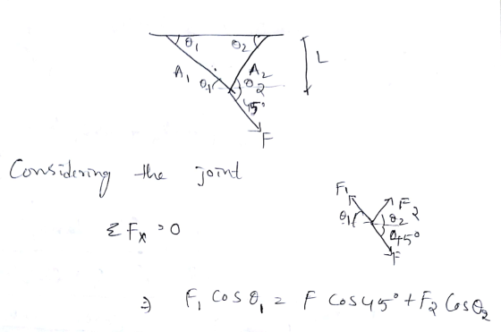
Problem #2 again the two-bar truss in the figure below, again subject to the concentrated load...
3. A two bar truss structure is shown in Figure 1. The coordinates of Points A, C and B are given...
 3. A two bar truss structure is shown in Figure 1. The coordinates of Points A, C and B are given by (0,0), (0, 10") and (10",0), respectively, in which the x-axis is from A to B and the y-axis is from A to C. Points A and C are fixed. The cross-sectional area of all members in inch?. A vertical point load, P, is applied at the tip of the structure, Point B. Based upon either the Principle of...
Problem 1 The truss (all joints are pinned) structure in figure 1 is made of members with cross s...
 We were unable to transcribe this imageProblem 1 The truss (all joints are pinned) structure in figure 1 is made of members with cross sectional area A = 1 in, with a linear elastic, homogeneous, isotropic material with an elastic modulus. E-10E6 psi and a coefficient of thermal expansion, α-6E-6 °F-ι. The structure starts out at a uniform temperature of 65°F and is raised to a final temperature of 120°F while being subjected to a concentrated load Po- 5,000 lbs...
Grid 4 Grid 3 Po 15 in Grid 1 Grid 2 10 in Figure 1: Problem...
 Grid 4 Grid 3 Po 15 in Grid 1 Grid 2 10 in Figure 1: Problem 1 Schematic Problem 1 The truss (all joints are pinned) structure in figure 1 is made of members with cross sectional area A- 1 in2, with a linear elastic, homogeneous, isotropic material with an elastic modulus, E, 10E6 psi and a coefficient of thermal expansion. α-6E-6 op-1. The structure starts out at a uniform temperature of 65°F and is raised to a final temperature...
P16.52 Determine the maximum and minimum axial forces in member CH of the truss in Problem 16.45 given the following loading scenario: uniform dead load of 1 klf, a moving uniform live load of 2 klf,...
 P16.52 Determine the maximum and minimum axial forces in member CH of the truss in Problem 16.45 given the following loading scenario: uniform dead load of 1 klf, a moving uniform live load of 2 klf, a moving concentrated load of 20 k, and an impact factor of 30%. P16.45 BC, CH, HI, and CI. (Ans: load @ H: NBC=-1.78, MCH = 0.56) F G Problem 16.45
P16.52 Determine the maximum and minimum axial forces in member CH of the...
P16.52 Determine the maximum and minimum axial forces in member CH of the truss in Problem 16.45 given the following loading scenario: uniform dead load of 1 klf, a moving uniform live load of 2 klf, a moving concentrated load of 20 k, and an impact factor of 30%. P16.45 BC, CH, HI, and CI. (Ans: load @ H: NBC=-1.78, MCH = 0.56) F G Problem 16.45
P16.52 Determine the maximum and minimum axial forces in member CH of the...
two-member truss is subjected to a load P 8000 N. Me mber 1-2 is 400 mm...
 two-member truss is subjected to a load P 8000 N. Me mber 1-2 is 400 mm long. 4.12. A ember 1-3 was manufactured to be 505 mm long instead of 500 mm. However, it was forced into place. Determine stresses in the members assuming that member 1-3 was manufactured to its correct (a) the length of 500 mm load P, of course). pression in the text.) Take cross-sectional areas 750 mm2, E 200 GPa (b) thestresses in the members as...
Problem 2: The figure below shows a two-member plane truss supported by a linearly elastic spring....
 Problem 2: The figure below shows a two-member plane truss supported by a linearly elastic spring. The truss members are of a solid circular cross section having diameter, d = 20mm, and E = 80 GPa. The linear spring has a stiffness constant of 50 N/mm. A load of 15 kN is applied at 3 at an angle of 50 degrees with the horizontal. Find (a) The global displacements of the unconstrained node and (b) compute the reaction forces and...
Problem 1) A load, P, is supported by a structure consisting of rigid bar BDF and...
 Problem 1) A load, P, is supported by a structure consisting of rigid bar BDF and three identical rods (cross-sectional area, A length, L; and elastic modulus, E), as shown. Load P is offset from the left bar by distance, c. Bars 1 and 2 are separated by distance, a; bars 2 and 3 are separated by distance, b. Symbolically (using the necessary variables) derive the three equations necessary to solve for the forces (Fi, F2, and F3) in the...
Technical Mechanics Course work: Problem 1. Input data: Rigid body (a x b) is connected with immovable base by plane bar system (plane truss) and loaded by plane forces. The sizes and load components are given below (table 1 and schemes).
 Technical MechanicsCourse work: Problem 1.Input data: Rigid body (a x b) is connected with immovable base by plane bar system (plane truss) and loaded by plane forces. The sizes and load components are given below (table 1 and schemes).Define: Internal force of bars and reaction of supportsVar.Nr13.a, m2.2b, m1.7M1, kNm3.5F1, kNF2, kNq, kN/m2.44.51.5
Problem 2 Consider a simply supported symmetric I beam ABCD carrying a uniformly distributed load w and a concentrated...
 Problem 2 Consider a simply supported symmetric I beam ABCD carrying a uniformly distributed load w and a concentrated load F as shown in Figure 2. Young's modulus of the beam is 200 GPa F- 8 kNN 8cm 3cm 3cm w- 6 kN/m 6cm 2cm Figure 2 1) Replace the support C with the reaction force Rc, and using static equilibrium find the reactions at point A and B in terms of Ro 2) Using the boundary conditions, calculate the...
Solve the following truss problem. All truss members are ANSI 2x2x0.25 hollow square tubes (with rounded...
 Solve the following truss problem. All truss members are ANSI 2x2x0.25 hollow square tubes (with rounded corners) for which the cross-section area is A-1.5891 in2. The material has a modulus of E-29E6 psi. Length of element 1 and 5 is L-20 inches, and length of element 3 and 6 is 2L 40 inches. 7 5 6 P-1000 lb 2. 1. Solve in an Excel spreadsheet using the truss element. Note that there are only four different element stiffness matrices (look...
 3. A two bar truss structure is shown in Figure 1. The coordinates of Points A, C and B are given by (0,0), (0, 10") and (10",0), respectively, in which the x-axis is from A to B and the y-axis is from A to C. Points A and C are fixed. The cross-sectional area of all members in inch?. A vertical point load, P, is applied at the tip of the structure, Point B. Based upon either the Principle of...
 We were unable to transcribe this imageProblem 1 The truss (all joints are pinned) structure in figure 1 is made of members with cross sectional area A = 1 in, with a linear elastic, homogeneous, isotropic material with an elastic modulus. E-10E6 psi and a coefficient of thermal expansion, α-6E-6 °F-ι. The structure starts out at a uniform temperature of 65°F and is raised to a final temperature of 120°F while being subjected to a concentrated load Po- 5,000 lbs...
 Grid 4 Grid 3 Po 15 in Grid 1 Grid 2 10 in Figure 1: Problem 1 Schematic Problem 1 The truss (all joints are pinned) structure in figure 1 is made of members with cross sectional area A- 1 in2, with a linear elastic, homogeneous, isotropic material with an elastic modulus, E, 10E6 psi and a coefficient of thermal expansion. α-6E-6 op-1. The structure starts out at a uniform temperature of 65°F and is raised to a final temperature...
 P16.52 Determine the maximum and minimum axial forces in member CH of the truss in Problem 16.45 given the following loading scenario: uniform dead load of 1 klf, a moving uniform live load of 2 klf, a moving concentrated load of 20 k, and an impact factor of 30%. P16.45 BC, CH, HI, and CI. (Ans: load @ H: NBC=-1.78, MCH = 0.56) F G Problem 16.45
P16.52 Determine the maximum and minimum axial forces in member CH of the...
P16.52 Determine the maximum and minimum axial forces in member CH of the truss in Problem 16.45 given the following loading scenario: uniform dead load of 1 klf, a moving uniform live load of 2 klf, a moving concentrated load of 20 k, and an impact factor of 30%. P16.45 BC, CH, HI, and CI. (Ans: load @ H: NBC=-1.78, MCH = 0.56) F G Problem 16.45
P16.52 Determine the maximum and minimum axial forces in member CH of the...
 two-member truss is subjected to a load P 8000 N. Me mber 1-2 is 400 mm long. 4.12. A ember 1-3 was manufactured to be 505 mm long instead of 500 mm. However, it was forced into place. Determine stresses in the members assuming that member 1-3 was manufactured to its correct (a) the length of 500 mm load P, of course). pression in the text.) Take cross-sectional areas 750 mm2, E 200 GPa (b) thestresses in the members as...
 Problem 2: The figure below shows a two-member plane truss supported by a linearly elastic spring. The truss members are of a solid circular cross section having diameter, d = 20mm, and E = 80 GPa. The linear spring has a stiffness constant of 50 N/mm. A load of 15 kN is applied at 3 at an angle of 50 degrees with the horizontal. Find (a) The global displacements of the unconstrained node and (b) compute the reaction forces and...
 Problem 1) A load, P, is supported by a structure consisting of rigid bar BDF and three identical rods (cross-sectional area, A length, L; and elastic modulus, E), as shown. Load P is offset from the left bar by distance, c. Bars 1 and 2 are separated by distance, a; bars 2 and 3 are separated by distance, b. Symbolically (using the necessary variables) derive the three equations necessary to solve for the forces (Fi, F2, and F3) in the...
 Problem 2 Consider a simply supported symmetric I beam ABCD carrying a uniformly distributed load w and a concentrated load F as shown in Figure 2. Young's modulus of the beam is 200 GPa F- 8 kNN 8cm 3cm 3cm w- 6 kN/m 6cm 2cm Figure 2 1) Replace the support C with the reaction force Rc, and using static equilibrium find the reactions at point A and B in terms of Ro 2) Using the boundary conditions, calculate the...
 Solve the following truss problem. All truss members are ANSI 2x2x0.25 hollow square tubes (with rounded corners) for which the cross-section area is A-1.5891 in2. The material has a modulus of E-29E6 psi. Length of element 1 and 5 is L-20 inches, and length of element 3 and 6 is 2L 40 inches. 7 5 6 P-1000 lb 2. 1. Solve in an Excel spreadsheet using the truss element. Note that there are only four different element stiffness matrices (look...
Most questions answered within 3 hours.
-
Where is the error in this code sequence?
String s1 = "Hello";
String s2 = "ello";...
asked 10 months ago -
Financial data for Joel de Paris, Inc., for last year
follow:
Joel de Paris, Inc.
Balance...
asked 10 months ago -
Consider this reaction:
Al2(SO4)3 (aq)+ BaCl3
(aq) Al2Cl6 (aq)- +
3BaSO4(s) . What is the...
asked 10 months ago -
Suppose that Savneet is considering increasing her
recent random sample from 20 car rentals to 40...
asked 10 months ago -
Trucks arrive at an unloading terminal at an average rate of 120
per hour.
Trucks arrive...
asked 10 months ago -
Why are methanol and ethanol completely soluble in water while
octanol is not very little soluble....
asked 10 months ago -
A facilities manager at a university reads in a research report
that the mean amount of...
asked 10 months ago -
When the CuSO4 is rehydrated by adding water to the anhydrous
compound, is this an endothermic...
asked 10 months ago -
A ray of sunlight is passing from diamond into crown glass; the
angle of incidence is...
asked 10 months ago -
A block of mass 0.249 kg is placed on top of a light, vertical
spring of...
asked 10 months ago -
how do the kidneys compensate in the presences of acidosis
a) trigger hyperventilate
b) reserve acid...
asked 10 months ago -
Question 501 pts
The rental rate of capital to the firm increases. Which of the
following...
asked 10 months ago