
Homework Answers


Add Answer to:
2. The frame is supported by pin at A and roller at E. Find the components...
PlOBlem 4 (10 points) 2 m 3 m The frame is made up of members ACE, BCD and DE. The frame is pin- 6 m supported at A...
 PlOBlem 4 (10 points) 2 m 3 m The frame is made up of members ACE, BCD and DE. The frame is pin- 6 m supported at A and roller-supported at B. On member ACE, determine the 2 m magnitudes and directions of forces acting at pins C and E Hint: Begin with overall free body 3 m diagram 600 N 5 m
PlOBlem 4 (10 points) 2 m 3 m The frame is made up of members ACE, BCD...
PlOBlem 4 (10 points) 2 m 3 m The frame is made up of members ACE, BCD and DE. The frame is pin- 6 m supported at A and roller-supported at B. On member ACE, determine the 2 m magnitudes and directions of forces acting at pins C and E Hint: Begin with overall free body 3 m diagram 600 N 5 m
PlOBlem 4 (10 points) 2 m 3 m The frame is made up of members ACE, BCD...
Problem 1 (10 points) A truss is pin supported at A and roller supported at G The support reactions at A and G are...
 Problem 1 (10 points) A truss is pin supported at A and roller supported at G The support reactions at A and G are 15 ft A, ; 4500 lb A-0 lb G, 1500 lb 3000 lb 3000Ib Determine the forces in members BC, CD and C. State whether they are in compression or tension.
Problem 1 (10 points) A truss is pin supported at A and roller supported at G The support reactions at A and G are 15...
Problem 1 (10 points) A truss is pin supported at A and roller supported at G The support reactions at A and G are 15 ft A, ; 4500 lb A-0 lb G, 1500 lb 3000 lb 3000Ib Determine the forces in members BC, CD and C. State whether they are in compression or tension.
Problem 1 (10 points) A truss is pin supported at A and roller supported at G The support reactions at A and G are 15...
1. Consider the following system that consists of a rigid bar supported by a roller at...
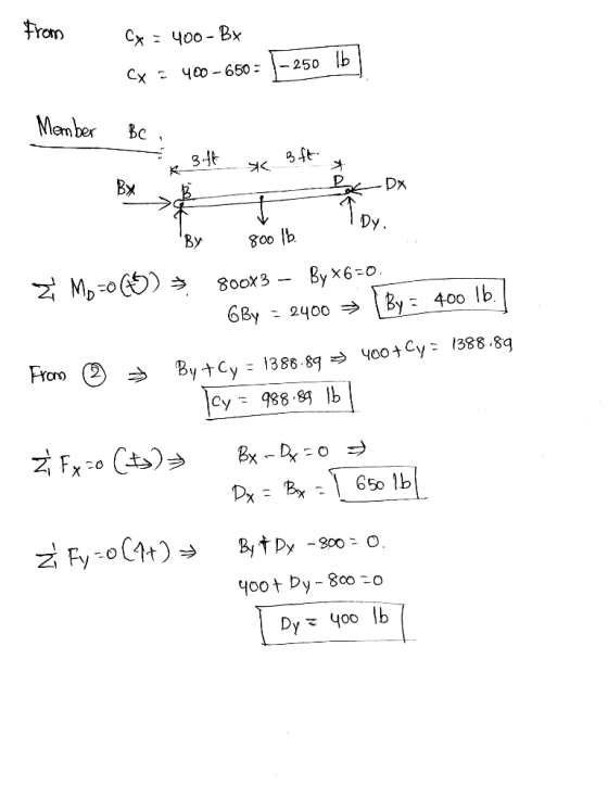
 1. Consider the following system that consists of a rigid bar supported by a roller at A and a pin at B Draw a free body diagram of the rigid body AB. Show the three equilibrium equations for the rigid body and circle them. Solve the system of equations to determine the reaction forces at A and B. a) b) c) 390 lb 800 lb ft 8 ft4 ft
The structure below is supported by a pin at A and a roller at E Determine the force in each memb...
 The structure below is supported by a pin at A and a roller at E Determine the force in each member of the truss using the Method of Joints H meters 2 FE m AH m GF m HG m Joint Loadings, kN ent length, m Height, m HG GF FE 1.5 2 Draw FBD of truss system to determine reaction forces Assume all forces in members are tensile. If answer is negative, force is compressive. s in x direction...
AB length is 4000mm AD length is 3000mm A pin jointed frame ABCD is supported by...
 AB length is 4000mm
AD length is 3000mm
A pin jointed frame ABCD is supported by a pinned support at A, a roller at B and is subjected to the loading indicated in Figure Q1. All members have circular cross-section and all are made of steel materials with same cross-section. Determine the support reactions at A and B Determine all the member forces Find out the horizontal displacement at point C using a table template as shown in Table Q1....
AB length is 4000mm
AD length is 3000mm
A pin jointed frame ABCD is supported by a pinned support at A, a roller at B and is subjected to the loading indicated in Figure Q1. All members have circular cross-section and all are made of steel materials with same cross-section. Determine the support reactions at A and B Determine all the member forces Find out the horizontal displacement at point C using a table template as shown in Table Q1....
The rigid frame shown below is supported by Pin A and Roller C.
 The rigid frame shown below is supported by Pin A and Roller C. [Point B is a rigid joint.] The frame supports a uniformly distributed load of 20 kN/m (downward) in Region BC, and a 250 kN point load (downward) located halfway between Pin A and rigid joint B. The modulus of elasticity of the entire frame is E = 200 GPa and the moment of inertia is I = 500 x 106 mm4. Determine the rotation (slope) at Joint...
In the following loaded truss, which is supported by pin at A and roller at B,...
 In the following loaded truss, which is supported by pin at A and roller at B, as shown a. Find Zero force Members by inspection (Negative marks for wrong answer) b. Find Support Reactions at A and B c. Find forces in Members CD and CE by Method of Section d. Find forces in Members EF and CH by Method of Joint (3 Points) (6 Points) (8 Points) (8 Points) 8U)N 800 N 800N D600 N 60 11.547 m 30°...
60 E pin O roller 9. [1pt] Two forces are applied to the truss as shown,...
 60 E pin O roller 9. [1pt] Two forces are applied to the truss as shown, Fi = 128 N and F2 = 164 N. The truss is supported by a pin joint at A and a roller at E. Assume L = 1.30 m. Indicate whether the member AD is in compression (C) or in tension (T). You only have I try! Answer: Submit All Answers 10. [1pt] Calculate the value of the force in member CD. Enter a...
Figure Q5(b) shows a frame ABCDE that is supported by a hinge at A and E...
 Figure Q5(b) shows a frame ABCDE that is supported by a hinge at A and E b) ) Construct the free body diagram for the entire structure, the disc and member DBE t) By applying equation of equilibrium, determine the horizontal and vertical components of the force that is acting on the hinge of member DBE il) if the weight of the cylinder is increased to 60 N and all the reaction forces are remain unchanged evaluate the new radius...
6.32 through 6.38 Determine the components of the forces acting on each member of the pin-connected...
 6.32 through 6.38 Determine the components of the forces acting on each member of the pin-connected frame shown. r = 1 ft 4 ft 3 ft 2 ft Joha 2.0 kip - 4 f 4 ft PROB. 6.37
 PlOBlem 4 (10 points) 2 m 3 m The frame is made up of members ACE, BCD and DE. The frame is pin- 6 m supported at A and roller-supported at B. On member ACE, determine the 2 m magnitudes and directions of forces acting at pins C and E Hint: Begin with overall free body 3 m diagram 600 N 5 m
PlOBlem 4 (10 points) 2 m 3 m The frame is made up of members ACE, BCD...
PlOBlem 4 (10 points) 2 m 3 m The frame is made up of members ACE, BCD and DE. The frame is pin- 6 m supported at A and roller-supported at B. On member ACE, determine the 2 m magnitudes and directions of forces acting at pins C and E Hint: Begin with overall free body 3 m diagram 600 N 5 m
PlOBlem 4 (10 points) 2 m 3 m The frame is made up of members ACE, BCD...
 Problem 1 (10 points) A truss is pin supported at A and roller supported at G The support reactions at A and G are 15 ft A, ; 4500 lb A-0 lb G, 1500 lb 3000 lb 3000Ib Determine the forces in members BC, CD and C. State whether they are in compression or tension.
Problem 1 (10 points) A truss is pin supported at A and roller supported at G The support reactions at A and G are 15...
Problem 1 (10 points) A truss is pin supported at A and roller supported at G The support reactions at A and G are 15 ft A, ; 4500 lb A-0 lb G, 1500 lb 3000 lb 3000Ib Determine the forces in members BC, CD and C. State whether they are in compression or tension.
Problem 1 (10 points) A truss is pin supported at A and roller supported at G The support reactions at A and G are 15...
 1. Consider the following system that consists of a rigid bar supported by a roller at A and a pin at B Draw a free body diagram of the rigid body AB. Show the three equilibrium equations for the rigid body and circle them. Solve the system of equations to determine the reaction forces at A and B. a) b) c) 390 lb 800 lb ft 8 ft4 ft
 The structure below is supported by a pin at A and a roller at E Determine the force in each member of the truss using the Method of Joints H meters 2 FE m AH m GF m HG m Joint Loadings, kN ent length, m Height, m HG GF FE 1.5 2 Draw FBD of truss system to determine reaction forces Assume all forces in members are tensile. If answer is negative, force is compressive. s in x direction...
 AB length is 4000mm
AD length is 3000mm
A pin jointed frame ABCD is supported by a pinned support at A, a roller at B and is subjected to the loading indicated in Figure Q1. All members have circular cross-section and all are made of steel materials with same cross-section. Determine the support reactions at A and B Determine all the member forces Find out the horizontal displacement at point C using a table template as shown in Table Q1....
AB length is 4000mm
AD length is 3000mm
A pin jointed frame ABCD is supported by a pinned support at A, a roller at B and is subjected to the loading indicated in Figure Q1. All members have circular cross-section and all are made of steel materials with same cross-section. Determine the support reactions at A and B Determine all the member forces Find out the horizontal displacement at point C using a table template as shown in Table Q1....
 In the following loaded truss, which is supported by pin at A and roller at B, as shown a. Find Zero force Members by inspection (Negative marks for wrong answer) b. Find Support Reactions at A and B c. Find forces in Members CD and CE by Method of Section d. Find forces in Members EF and CH by Method of Joint (3 Points) (6 Points) (8 Points) (8 Points) 8U)N 800 N 800N D600 N 60 11.547 m 30°...
 60 E pin O roller 9. [1pt] Two forces are applied to the truss as shown, Fi = 128 N and F2 = 164 N. The truss is supported by a pin joint at A and a roller at E. Assume L = 1.30 m. Indicate whether the member AD is in compression (C) or in tension (T). You only have I try! Answer: Submit All Answers 10. [1pt] Calculate the value of the force in member CD. Enter a...
 Figure Q5(b) shows a frame ABCDE that is supported by a hinge at A and E b) ) Construct the free body diagram for the entire structure, the disc and member DBE t) By applying equation of equilibrium, determine the horizontal and vertical components of the force that is acting on the hinge of member DBE il) if the weight of the cylinder is increased to 60 N and all the reaction forces are remain unchanged evaluate the new radius...
 6.32 through 6.38 Determine the components of the forces acting on each member of the pin-connected frame shown. r = 1 ft 4 ft 3 ft 2 ft Joha 2.0 kip - 4 f 4 ft PROB. 6.37
Most questions answered within 3 hours.
-
Where is the error in this code sequence?
String s1 = "Hello";
String s2 = "ello";...
asked 10 months ago -
Financial data for Joel de Paris, Inc., for last year
follow:
Joel de Paris, Inc.
Balance...
asked 10 months ago -
Consider this reaction:
Al2(SO4)3 (aq)+ BaCl3
(aq) Al2Cl6 (aq)- +
3BaSO4(s) . What is the...
asked 10 months ago -
Suppose that Savneet is considering increasing her
recent random sample from 20 car rentals to 40...
asked 10 months ago -
Trucks arrive at an unloading terminal at an average rate of 120
per hour.
Trucks arrive...
asked 10 months ago -
Why are methanol and ethanol completely soluble in water while
octanol is not very little soluble....
asked 10 months ago -
A facilities manager at a university reads in a research report
that the mean amount of...
asked 10 months ago -
When the CuSO4 is rehydrated by adding water to the anhydrous
compound, is this an endothermic...
asked 10 months ago -
A ray of sunlight is passing from diamond into crown glass; the
angle of incidence is...
asked 10 months ago -
A block of mass 0.249 kg is placed on top of a light, vertical
spring of...
asked 10 months ago -
how do the kidneys compensate in the presences of acidosis
a) trigger hyperventilate
b) reserve acid...
asked 10 months ago -
Question 501 pts
The rental rate of capital to the firm increases. Which of the
following...
asked 10 months ago