
Homework Answers

Add Answer to:
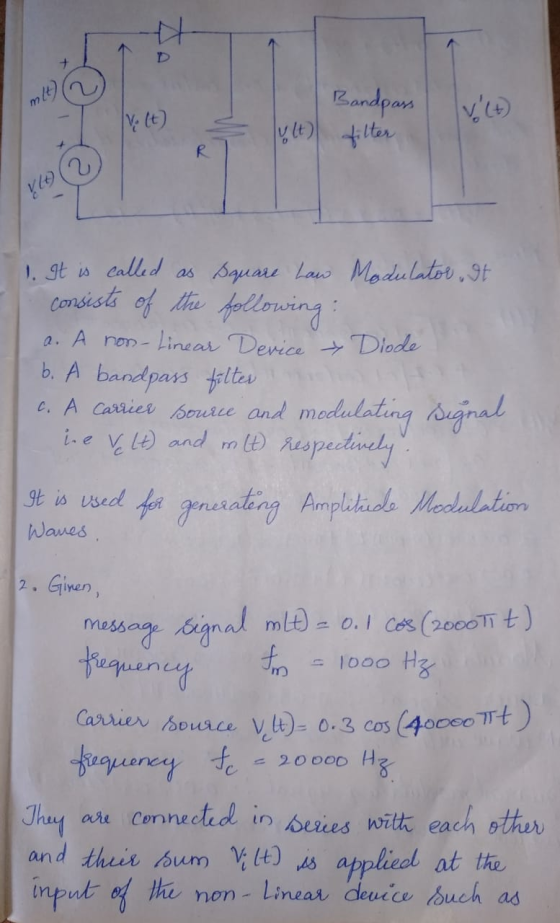
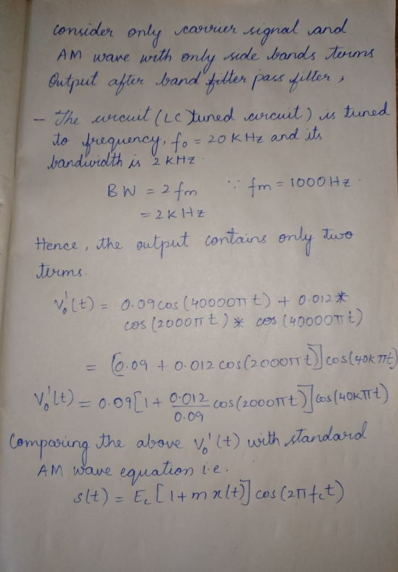
Q: One type of modulators is shown below: y(t) Rs 10 Bandpass filter von Vc(t) 1-...
5) Consider the following second-order bandpass filter. As input voltage, apply V(t) 100Ω, C-4.7 μF. and L-10mH. sin(wt).R in Vout Fig 9: Second-order band-pass filter a) Determine the frequenc...
 5) Consider the following second-order bandpass filter. As input voltage, apply V(t) 100Ω, C-4.7 μF. and L-10mH. sin(wt).R in Vout Fig 9: Second-order band-pass filter a) Determine the frequency response function H(ju) Ve-ju) / Vm(ju) and sketch the magnitude and phase characteristics versus w by calaulation. Calculate the theoretical cutoff frequency of the filter Using PSpice AC analysis, plot magnitude lHju)l and phase ф characteristics of the filter, between 1 Hz-100 KHz b) c)
5) Consider the following second-order bandpass...
5) Consider the following second-order bandpass filter. As input voltage, apply V(t) 100Ω, C-4.7 μF. and L-10mH. sin(wt).R in Vout Fig 9: Second-order band-pass filter a) Determine the frequency response function H(ju) Ve-ju) / Vm(ju) and sketch the magnitude and phase characteristics versus w by calaulation. Calculate the theoretical cutoff frequency of the filter Using PSpice AC analysis, plot magnitude lHju)l and phase ф characteristics of the filter, between 1 Hz-100 KHz b) c)
5) Consider the following second-order bandpass...
Consider the series RLC bandpass filter shown in (Figure 1). The filter has a quality of...
 Consider the series RLC bandpass filter shown in (Figure 1). The filter has a quality of 2 and a center frequency of 8 kHz. The input to the filter is vi (t) = 23 cos wt V. Suppose that C = 5 nF. Figure < 1 of 1 + VLC с L HE + + Vi R} R V. Part E Find the voltage drop across the series combination of the inductor and capacitor when w=10w, Suppose that vlc (t)...
1. The system shown is used for scrambling audio signals. The output signal, y(t) is the...
 1. The system shown is used for scrambling audio signals. The output signal, y(t) is the scrambled version of the input m(t). Find the spectrum of the scrambled signal y(t): Y(f) Mf) m(t) vt) Low-pass filter 0-15 kHz - (Scrambled output) - 15 kHz | 15 kHz f kHz 2 cos 30,000 t
choose one of the multiple choice answers above. please show all work Question: 10 CIRCUIT Y...
 choose one of the multiple choice answers above.
please show all work
Question: 10 CIRCUIT Y FIG.10 (5 Marks) Statement: Consider the RC-coupled amplifier circuit illustrated in Fig. 10 (CIRCUIT Y). Sketching relevant output (Vc-Ic) characteristics, decide Q-point coordinates and DC load-line details (of the NPN-BJT/Si circuit of Fig. 10 of Circuit Y). Further, establish an appropriate AC-load line and decide the maximum swing of the output voltage across Rload with respect to the Q-point. Assume the input signal at...
choose one of the multiple choice answers above.
please show all work
Question: 10 CIRCUIT Y FIG.10 (5 Marks) Statement: Consider the RC-coupled amplifier circuit illustrated in Fig. 10 (CIRCUIT Y). Sketching relevant output (Vc-Ic) characteristics, decide Q-point coordinates and DC load-line details (of the NPN-BJT/Si circuit of Fig. 10 of Circuit Y). Further, establish an appropriate AC-load line and decide the maximum swing of the output voltage across Rload with respect to the Q-point. Assume the input signal at...
please pick one of the multiple choice options above. show all work, thank you Question 9...
 please pick one of the multiple choice options above.
show all work, thank you
Question 9 CIRCUIT X/FIG.9 (5 Marks) Statement: Consider the RC-coupled amplifier circuit illustrated in Fig. 9 (CIRCUIT X). Sketching relevant output (Vc-Ic) characteristics that decide Q-point coordinates and DC load-line details (of the NPN-BJT/Si circuit of Fig. 9 of Circuit X) Further, establish an appropriate AC-load line and decide the maximum swing of the output voltage across Rload with respect to the Q-point. Assume the input...
please pick one of the multiple choice options above.
show all work, thank you
Question 9 CIRCUIT X/FIG.9 (5 Marks) Statement: Consider the RC-coupled amplifier circuit illustrated in Fig. 9 (CIRCUIT X). Sketching relevant output (Vc-Ic) characteristics that decide Q-point coordinates and DC load-line details (of the NPN-BJT/Si circuit of Fig. 9 of Circuit X) Further, establish an appropriate AC-load line and decide the maximum swing of the output voltage across Rload with respect to the Q-point. Assume the input...
 5) Consider the following second-order bandpass filter. As input voltage, apply V(t) 100Ω, C-4.7 μF. and L-10mH. sin(wt).R in Vout Fig 9: Second-order band-pass filter a) Determine the frequency response function H(ju) Ve-ju) / Vm(ju) and sketch the magnitude and phase characteristics versus w by calaulation. Calculate the theoretical cutoff frequency of the filter Using PSpice AC analysis, plot magnitude lHju)l and phase ф characteristics of the filter, between 1 Hz-100 KHz b) c)
5) Consider the following second-order bandpass...
5) Consider the following second-order bandpass filter. As input voltage, apply V(t) 100Ω, C-4.7 μF. and L-10mH. sin(wt).R in Vout Fig 9: Second-order band-pass filter a) Determine the frequency response function H(ju) Ve-ju) / Vm(ju) and sketch the magnitude and phase characteristics versus w by calaulation. Calculate the theoretical cutoff frequency of the filter Using PSpice AC analysis, plot magnitude lHju)l and phase ф characteristics of the filter, between 1 Hz-100 KHz b) c)
5) Consider the following second-order bandpass...
 Consider the series RLC bandpass filter shown in (Figure 1). The filter has a quality of 2 and a center frequency of 8 kHz. The input to the filter is vi (t) = 23 cos wt V. Suppose that C = 5 nF. Figure < 1 of 1 + VLC с L HE + + Vi R} R V. Part E Find the voltage drop across the series combination of the inductor and capacitor when w=10w, Suppose that vlc (t)...
 1. The system shown is used for scrambling audio signals. The output signal, y(t) is the scrambled version of the input m(t). Find the spectrum of the scrambled signal y(t): Y(f) Mf) m(t) vt) Low-pass filter 0-15 kHz - (Scrambled output) - 15 kHz | 15 kHz f kHz 2 cos 30,000 t
 choose one of the multiple choice answers above.
please show all work
Question: 10 CIRCUIT Y FIG.10 (5 Marks) Statement: Consider the RC-coupled amplifier circuit illustrated in Fig. 10 (CIRCUIT Y). Sketching relevant output (Vc-Ic) characteristics, decide Q-point coordinates and DC load-line details (of the NPN-BJT/Si circuit of Fig. 10 of Circuit Y). Further, establish an appropriate AC-load line and decide the maximum swing of the output voltage across Rload with respect to the Q-point. Assume the input signal at...
choose one of the multiple choice answers above.
please show all work
Question: 10 CIRCUIT Y FIG.10 (5 Marks) Statement: Consider the RC-coupled amplifier circuit illustrated in Fig. 10 (CIRCUIT Y). Sketching relevant output (Vc-Ic) characteristics, decide Q-point coordinates and DC load-line details (of the NPN-BJT/Si circuit of Fig. 10 of Circuit Y). Further, establish an appropriate AC-load line and decide the maximum swing of the output voltage across Rload with respect to the Q-point. Assume the input signal at...
 please pick one of the multiple choice options above.
show all work, thank you
Question 9 CIRCUIT X/FIG.9 (5 Marks) Statement: Consider the RC-coupled amplifier circuit illustrated in Fig. 9 (CIRCUIT X). Sketching relevant output (Vc-Ic) characteristics that decide Q-point coordinates and DC load-line details (of the NPN-BJT/Si circuit of Fig. 9 of Circuit X) Further, establish an appropriate AC-load line and decide the maximum swing of the output voltage across Rload with respect to the Q-point. Assume the input...
please pick one of the multiple choice options above.
show all work, thank you
Question 9 CIRCUIT X/FIG.9 (5 Marks) Statement: Consider the RC-coupled amplifier circuit illustrated in Fig. 9 (CIRCUIT X). Sketching relevant output (Vc-Ic) characteristics that decide Q-point coordinates and DC load-line details (of the NPN-BJT/Si circuit of Fig. 9 of Circuit X) Further, establish an appropriate AC-load line and decide the maximum swing of the output voltage across Rload with respect to the Q-point. Assume the input...
Most questions answered within 3 hours.
-
Where is the error in this code sequence?
String s1 = "Hello";
String s2 = "ello";...
asked 11 months ago -
Financial data for Joel de Paris, Inc., for last year
follow:
Joel de Paris, Inc.
Balance...
asked 11 months ago -
Consider this reaction:
Al2(SO4)3 (aq)+ BaCl3
(aq) Al2Cl6 (aq)- +
3BaSO4(s) . What is the...
asked 11 months ago -
Suppose that Savneet is considering increasing her
recent random sample from 20 car rentals to 40...
asked 11 months ago -
Trucks arrive at an unloading terminal at an average rate of 120
per hour.
Trucks arrive...
asked 11 months ago -
Why are methanol and ethanol completely soluble in water while
octanol is not very little soluble....
asked 11 months ago -
A facilities manager at a university reads in a research report
that the mean amount of...
asked 11 months ago -
When the CuSO4 is rehydrated by adding water to the anhydrous
compound, is this an endothermic...
asked 11 months ago -
A ray of sunlight is passing from diamond into crown glass; the
angle of incidence is...
asked 11 months ago -
A block of mass 0.249 kg is placed on top of a light, vertical
spring of...
asked 11 months ago -
how do the kidneys compensate in the presences of acidosis
a) trigger hyperventilate
b) reserve acid...
asked 11 months ago -
Question 501 pts
The rental rate of capital to the firm increases. Which of the
following...
asked 11 months ago