
Homework Answers


Add Answer to:
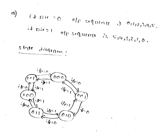
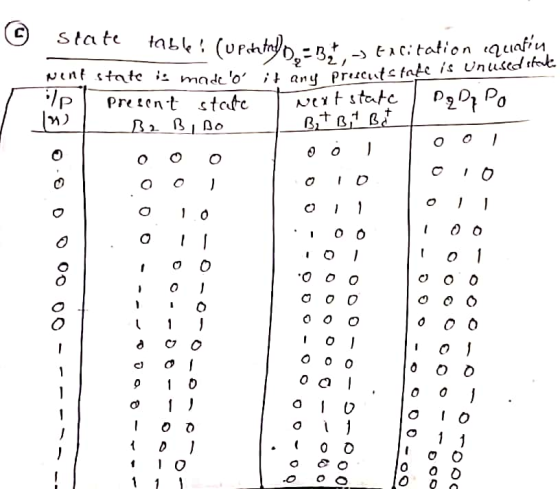
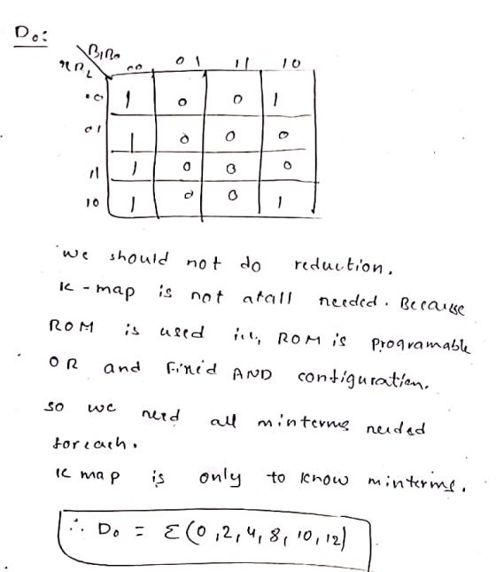
3. Finite State Machine. Using a ROM based finite state machine (FSM), design a bi-directional repetitive...
4) (3 points) You are asked to design a finite state machine (FSM) to control the...
 4) (3 points) You are asked to design a finite state machine (FSM) to control the tail-light of a 1965 Ford Thunderbird automobile. There are three lights on each side: i) Left: LA, LB, LC; ii) Right: RA, RB, RC. Corresponding to a Left (L) or a Right (R) turn signal, the flashing sequence is as shown in the figure below. [For example, when the left turn signal is activated, all the lights are off, then LA turns on, then...
Finite state machine (FSM) counter design: Gray codes have a useful property in that consecutive numbers differ in only a single bit position. Table 1 lists a 3-bit modulo 8 Gray code representing the...
 Finite state machine (FSM) counter design: Gray
codes have a useful property in that consecutive numbers differ in
only a single bit position. Table 1 lists a 3-bit modulo 8 Gray
code representing the numbers 0 to 7. Design a 3-bit modulo 8 Gray
code counter FSM.
a) First design and sketch a 3-bit modulo 8 Gray code counter
FSM with no inputs and three outputs, the 3-bit signal
Q2:0. (A modulo N counter counts from 0 to N −...
Finite state machine (FSM) counter design: Gray
codes have a useful property in that consecutive numbers differ in
only a single bit position. Table 1 lists a 3-bit modulo 8 Gray
code representing the numbers 0 to 7. Design a 3-bit modulo 8 Gray
code counter FSM.
a) First design and sketch a 3-bit modulo 8 Gray code counter
FSM with no inputs and three outputs, the 3-bit signal
Q2:0. (A modulo N counter counts from 0 to N −...
In this lab, you will design a finite state machine to control the tail lights of...
 In this lab, you will design a finite state machine to control the tail lights of an unsual car. There are three lights on each side that operate in sequence to indicate thedirection of a turn. Figure ! shows the tail lights and Figure 2 shows the flashing sequence for (a) left turns and (b) right rums. ZOTTAS Figure 28:8: BCECECece BCECECECes BCECECECB BCECECBCB 8888 Figure 2 Part 1 - FSM Design Start with designing the state transition diagram for...
Design a Mealy FSM which functions as a sequence detector, generating two outputs y, z in...
Design a Mealy FSM which functions as a sequence detector, generating two outputs y, z in the following way: a) The signal is applied sequentially to a single input line x. b) Initially both outputs y, z are set to 0. c) Output y is set to 1 when the sequence "10" has been applied to the input x; it should then be reset to 0 and the circuit should continue detecting next occurrence of "10". d) Output z is...
Design a finite state machine for a traffic light at the intersection of north-south traffic and...
Design a finite state machine for a traffic light at the intersection of north-south traffic and east-west traffic. The light can be red, green or yellow. Assume a 30 second clock. Assume that the light will change only if a car is coming in the other direction. If cars are in both north-south and east-west, the light will change from one direction to the other. What are the machine states? What are the inputs? What are the outputs? Draw state...
Design a finite state machine for a traffic light at the intersection of north-south traffic and...
 Design a finite state machine for a traffic light at the intersection of north-south traffic and east-west traffic. The light can be red, green or yellow. Assume a 30 second clock. Assume that the light will change only if a car is coming in the other direction. If cars are in both north-south and east-west, the light will change from one direction to the other. What are the machine states? What are the inputs? What are the outputs? Draw state...
6. (a) Each clock cycle, an input is provided to the finite state machine (FSM) below....
 6. (a) Each clock cycle, an input is provided to the finite
state machine (FSM) below. Assuming that we start at state 00 and
given an input for each tick, fill in the table to show the next
state.
(b) What bit sequence(s) does this FSM recognize? Your answer
should be a string of bits (ex. “01” or “1110”).
11 0- 10 00 01 Time 0 1 2 3 4 5 6 input START 1 0 0 1 1 0...
6. (a) Each clock cycle, an input is provided to the finite
state machine (FSM) below. Assuming that we start at state 00 and
given an input for each tick, fill in the table to show the next
state.
(b) What bit sequence(s) does this FSM recognize? Your answer
should be a string of bits (ex. “01” or “1110”).
11 0- 10 00 01 Time 0 1 2 3 4 5 6 input START 1 0 0 1 1 0...
Pre-Laboratorv Exercise: You are to design a state machine capable of controlling a 4-phase unipo...
 Pre-Laboratorv Exercise: You are to design a state machine capable of controlling a 4-phase unipolar stepper motor. This motor operates by energizing one (or more) of four coils of wire at a time to rotate a magnetized shaft to predetermined positions. Let us call the four coils A, B, C, and D. To make the motor rotate properly, the coils need to be turned on (driven at logic "1") and off (driven at logic "O") in the following sequence: ABCD-...
0/3 D6.15 Write an assembly main program that implements this Mealy finite state machine. happy The FSM state graph...
 0/3 D6.15 Write an assembly main program that implements this Mealy finite state machine. happy The FSM state graph, shown below, is givenP and cannot be changed. The input is on Port A bit 0 and the output is on Port B bits 3,2,1,0. There are three states (happy, hungry, sleepy), and initial state is happy. hungry 1/8 1/2 143 0/4 sleepy a) Show the ROM-based FSM data structure b) Show the initialization and controller software. Initialize the direction registers,...
Consider a finite state machine with a control input called mode. When mode = 0, the...
Consider a finite state machine with a control input called mode. When mode = 0, the machine operates as a mod-3 down counter, where the outputs are the count values. When mode = 1, the machine's output progresses through 1133 number (1 digit per clock cycle). Complete each of the steps which follow. (a) Draw the state diagram for this machine. (b) Write RTL Verilog code which implements this design. Submit your printed source code by the due date and...
 4) (3 points) You are asked to design a finite state machine (FSM) to control the tail-light of a 1965 Ford Thunderbird automobile. There are three lights on each side: i) Left: LA, LB, LC; ii) Right: RA, RB, RC. Corresponding to a Left (L) or a Right (R) turn signal, the flashing sequence is as shown in the figure below. [For example, when the left turn signal is activated, all the lights are off, then LA turns on, then...
 Finite state machine (FSM) counter design: Gray
codes have a useful property in that consecutive numbers differ in
only a single bit position. Table 1 lists a 3-bit modulo 8 Gray
code representing the numbers 0 to 7. Design a 3-bit modulo 8 Gray
code counter FSM.
a) First design and sketch a 3-bit modulo 8 Gray code counter
FSM with no inputs and three outputs, the 3-bit signal
Q2:0. (A modulo N counter counts from 0 to N −...
Finite state machine (FSM) counter design: Gray
codes have a useful property in that consecutive numbers differ in
only a single bit position. Table 1 lists a 3-bit modulo 8 Gray
code representing the numbers 0 to 7. Design a 3-bit modulo 8 Gray
code counter FSM.
a) First design and sketch a 3-bit modulo 8 Gray code counter
FSM with no inputs and three outputs, the 3-bit signal
Q2:0. (A modulo N counter counts from 0 to N −...
 In this lab, you will design a finite state machine to control the tail lights of an unsual car. There are three lights on each side that operate in sequence to indicate thedirection of a turn. Figure ! shows the tail lights and Figure 2 shows the flashing sequence for (a) left turns and (b) right rums. ZOTTAS Figure 28:8: BCECECece BCECECECes BCECECECB BCECECBCB 8888 Figure 2 Part 1 - FSM Design Start with designing the state transition diagram for...
 Design a finite state machine for a traffic light at the intersection of north-south traffic and east-west traffic. The light can be red, green or yellow. Assume a 30 second clock. Assume that the light will change only if a car is coming in the other direction. If cars are in both north-south and east-west, the light will change from one direction to the other. What are the machine states? What are the inputs? What are the outputs? Draw state...
 6. (a) Each clock cycle, an input is provided to the finite
state machine (FSM) below. Assuming that we start at state 00 and
given an input for each tick, fill in the table to show the next
state.
(b) What bit sequence(s) does this FSM recognize? Your answer
should be a string of bits (ex. “01” or “1110”).
11 0- 10 00 01 Time 0 1 2 3 4 5 6 input START 1 0 0 1 1 0...
6. (a) Each clock cycle, an input is provided to the finite
state machine (FSM) below. Assuming that we start at state 00 and
given an input for each tick, fill in the table to show the next
state.
(b) What bit sequence(s) does this FSM recognize? Your answer
should be a string of bits (ex. “01” or “1110”).
11 0- 10 00 01 Time 0 1 2 3 4 5 6 input START 1 0 0 1 1 0...
 Pre-Laboratorv Exercise: You are to design a state machine capable of controlling a 4-phase unipolar stepper motor. This motor operates by energizing one (or more) of four coils of wire at a time to rotate a magnetized shaft to predetermined positions. Let us call the four coils A, B, C, and D. To make the motor rotate properly, the coils need to be turned on (driven at logic "1") and off (driven at logic "O") in the following sequence: ABCD-...
 0/3 D6.15 Write an assembly main program that implements this Mealy finite state machine. happy The FSM state graph, shown below, is givenP and cannot be changed. The input is on Port A bit 0 and the output is on Port B bits 3,2,1,0. There are three states (happy, hungry, sleepy), and initial state is happy. hungry 1/8 1/2 143 0/4 sleepy a) Show the ROM-based FSM data structure b) Show the initialization and controller software. Initialize the direction registers,...
Most questions answered within 3 hours.
-
Where is the error in this code sequence?
String s1 = "Hello";
String s2 = "ello";...
asked 11 months ago -
Financial data for Joel de Paris, Inc., for last year
follow:
Joel de Paris, Inc.
Balance...
asked 11 months ago -
Consider this reaction:
Al2(SO4)3 (aq)+ BaCl3
(aq) Al2Cl6 (aq)- +
3BaSO4(s) . What is the...
asked 11 months ago -
Suppose that Savneet is considering increasing her
recent random sample from 20 car rentals to 40...
asked 11 months ago -
Trucks arrive at an unloading terminal at an average rate of 120
per hour.
Trucks arrive...
asked 11 months ago -
Why are methanol and ethanol completely soluble in water while
octanol is not very little soluble....
asked 11 months ago -
A facilities manager at a university reads in a research report
that the mean amount of...
asked 11 months ago -
When the CuSO4 is rehydrated by adding water to the anhydrous
compound, is this an endothermic...
asked 11 months ago -
A ray of sunlight is passing from diamond into crown glass; the
angle of incidence is...
asked 11 months ago -
A block of mass 0.249 kg is placed on top of a light, vertical
spring of...
asked 11 months ago -
how do the kidneys compensate in the presences of acidosis
a) trigger hyperventilate
b) reserve acid...
asked 11 months ago -
Question 501 pts
The rental rate of capital to the firm increases. Which of the
following...
asked 11 months ago