
Homework Answers

Add Answer to:
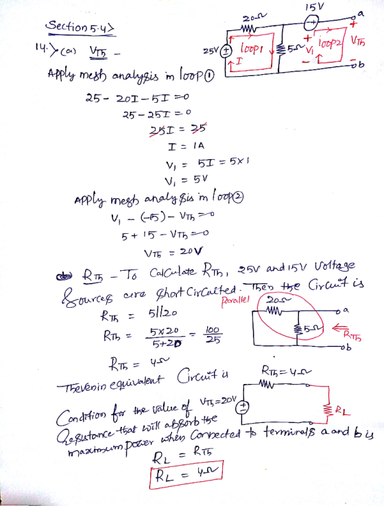
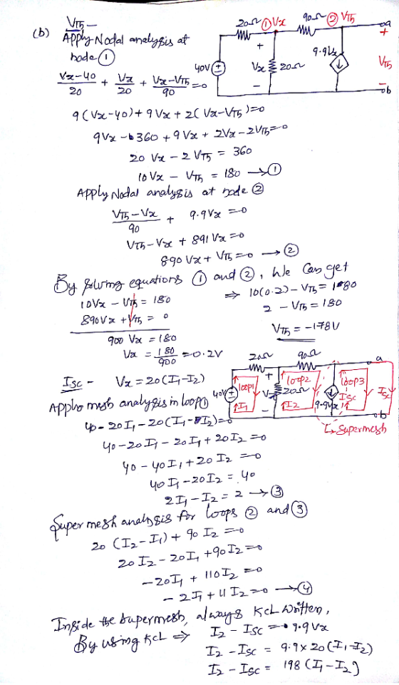
Section 5.4 14. Determine the valu the maximum power when ce mine the value of resistance...
PS - Determine the value of the resistance R below that would result in maximum power...
 PS - Determine the value of the resistance R below that would result in maximum power transfer then calculate that power. V, 300 100 $ 200
ame Su chool Number 4: : The source voltage of the circuit below is V()-140cos(30). The component values are RI-20, XL-30. Xc-20 a) Determine the load impedance Zab that will absorb maximum power if...
 ame Su chool Number 4: : The source voltage of the circuit below is V()-140cos(30). The component values are RI-20, XL-30. Xc-20 a) Determine the load impedance Zab that will absorb maximum power if it is connected to terminals a-b of the circuit below. b) Determine the maximum power absorbed by this load. Xc XL. M-0.8H R1 2-2 0.4H Vit)
ame Su chool Number 4: : The source voltage of the circuit below is V()-140cos(30). The component values are RI-20,...
ame Su chool Number 4: : The source voltage of the circuit below is V()-140cos(30). The component values are RI-20, XL-30. Xc-20 a) Determine the load impedance Zab that will absorb maximum power if it is connected to terminals a-b of the circuit below. b) Determine the maximum power absorbed by this load. Xc XL. M-0.8H R1 2-2 0.4H Vit)
ame Su chool Number 4: : The source voltage of the circuit below is V()-140cos(30). The component values are RI-20,...
Q5/// The maximum power dissipated in a 40 load is 100 w when connected to a...
 Q5/// The maximum power dissipated in a 40 load is 100 w when connected to a d.c. voltage V and internal resistance R. Calculate: the current in the load, internal resistance .R, and voltage V Q3/11 Some copper wire has a resistance of 200 Ohm at 20-C. A current is passed through the wire and the temperature rises to 90°C. Determine the resistance of the wire at 90°C, assuming that the temperature coefficient of resistance *.is 0.004/-C at 0°C
(5pts) 9. For the circuits shown below, the maximum power transfer occurs when the resistance of...
 (5pts) 9. For the circuits shown below, the maximum power transfer occurs when the resistance of R, is close to a. Ik b. 52 c. 5.5 k2 d. none of the above 1kΩ R. RS 1kΩ 10kΩ 10kΩ R2 + R3 5V Vo Ro 10V k R, 1ΚΩ (5pts) 10. The RMS value of a sine wave with peak-to-peak value of 10V is
would you like please answer all questions in part 3 THEVENIN'S THEOREM AND MAXIMUM POWER TRANSFER...
 would you like please answer all questions in part 3
THEVENIN'S THEOREM AND MAXIMUM POWER TRANSFER 131 Part 3 Maximum Power Transfer (Experimental Approach) (a) Construct the network of Fig. 11.8. Insert the measured value of each resistor R EIOV 95.732 218S2 325 2 . 424e R FIG. 11.8 Eths Vabs 6.8v Rths Resissn (b) The Thevenin equivalent circuit will now be determined for the network to the lel of the terminals a-b without disturbing the structure of the network....
would you like please answer all questions in part 3
THEVENIN'S THEOREM AND MAXIMUM POWER TRANSFER 131 Part 3 Maximum Power Transfer (Experimental Approach) (a) Construct the network of Fig. 11.8. Insert the measured value of each resistor R EIOV 95.732 218S2 325 2 . 424e R FIG. 11.8 Eths Vabs 6.8v Rths Resissn (b) The Thevenin equivalent circuit will now be determined for the network to the lel of the terminals a-b without disturbing the structure of the network....
Part 2 Maximum Power Transfer (Validating the Condition R = Rth) (a) Construct the network of...
 Part 2 Maximum Power Transfer (Validating the Condition R = Rth) (a) Construct the network of Fig. 11.7 and set the potentiometer to 50 2. Measure the voltage across R as you vary Rthrough the following values: 50, 100, 200, 300, 330, 400, 600, 800, and 1000 12. Be sure to set the resistance with the ohmmeter section of your meter be fore each reading. Remember to turn off the dc supply and disconnect one terminal of the po tentiometer...
Review Part A Determine the maximum normal stress in the bracket at section a-a when the...
 Review Part A Determine the maximum normal stress in the bracket at section a-a when the F 78 kN load is applied at = 0. (Figure 1) Express your answer with the appropriate units. Enter negative value in the case of compression and positive value in the case of tension. 7 1A ww Value Units Previous Answers Request Answen Submit X Incorrect; Try Again; 3 attempts remaining Figure 1 of 1 Part B 0. Determine the minimum normal stress in...
A Single-phase halfwave controlled rectifier is used for a heating system whose rated power is 15kW at 220V. The SCR is connected to a 220 VAC system. 1. Determine the rated equivalent resistance of the heater 2. Determine the maximum that the rectifie
 A Single-phase halfwave controlled rectifier is used for a heating system whose rated power is 15kW at 220V. The SCR is connected to a 220 VAC system. 1. Determine the rated equivalent resistance of the heater2. Determine the maximum that the rectifier can provide to the heater3. When the SCR is fired at angle of p/3, determinea. Waveform of the voltages across the load, the SCRb. Waveform of the currents flow through the SCR, drawn by the load and supplied...
EE 282-Circuit I Pre-Lab 9 Maximum Power Transfer Theorem Name Concepts: In this pre-lab we will ...
 EE 282-Circuit I Pre-Lab 9 Maximum Power Transfer Theorem Name Concepts: In this pre-lab we will be leaming about Maximum Power Transfer Theorem. Maximum power is transferred to the load when the load resistance equals the thexenin equivalent, and we carry out the analysis using Thevenin's equivalent circuit. In order to do this, first build the following circuit on Mutism. 1 R1 5.1k0 R3 2 V1 R2 8kQ 6.8㏀ Fig. 1 Part 1: To find the Thevenin equivalent resistance, we...
 PS - Determine the value of the resistance R below that would result in maximum power transfer then calculate that power. V, 300 100 $ 200
 ame Su chool Number 4: : The source voltage of the circuit below is V()-140cos(30). The component values are RI-20, XL-30. Xc-20 a) Determine the load impedance Zab that will absorb maximum power if it is connected to terminals a-b of the circuit below. b) Determine the maximum power absorbed by this load. Xc XL. M-0.8H R1 2-2 0.4H Vit)
ame Su chool Number 4: : The source voltage of the circuit below is V()-140cos(30). The component values are RI-20,...
ame Su chool Number 4: : The source voltage of the circuit below is V()-140cos(30). The component values are RI-20, XL-30. Xc-20 a) Determine the load impedance Zab that will absorb maximum power if it is connected to terminals a-b of the circuit below. b) Determine the maximum power absorbed by this load. Xc XL. M-0.8H R1 2-2 0.4H Vit)
ame Su chool Number 4: : The source voltage of the circuit below is V()-140cos(30). The component values are RI-20,...
 Q5/// The maximum power dissipated in a 40 load is 100 w when connected to a d.c. voltage V and internal resistance R. Calculate: the current in the load, internal resistance .R, and voltage V Q3/11 Some copper wire has a resistance of 200 Ohm at 20-C. A current is passed through the wire and the temperature rises to 90°C. Determine the resistance of the wire at 90°C, assuming that the temperature coefficient of resistance *.is 0.004/-C at 0°C
 Q5/// The maximum power dissipated in a 40 load is 100 w when connected to a d.c. voltage V and internal resistance R. Calculate: the current in the load, internal resistance .R, and voltage V Q3/11 Some copper wire has a resistance of 200 Ohm at 20-C. A current is passed through the wire and the temperature rises to 90°C. Determine the resistance of the wire at 90°C, assuming that the temperature coefficient of resistance *.is 0.004/-C at 0°C
 (5pts) 9. For the circuits shown below, the maximum power transfer occurs when the resistance of R, is close to a. Ik b. 52 c. 5.5 k2 d. none of the above 1kΩ R. RS 1kΩ 10kΩ 10kΩ R2 + R3 5V Vo Ro 10V k R, 1ΚΩ (5pts) 10. The RMS value of a sine wave with peak-to-peak value of 10V is
 would you like please answer all questions in part 3
THEVENIN'S THEOREM AND MAXIMUM POWER TRANSFER 131 Part 3 Maximum Power Transfer (Experimental Approach) (a) Construct the network of Fig. 11.8. Insert the measured value of each resistor R EIOV 95.732 218S2 325 2 . 424e R FIG. 11.8 Eths Vabs 6.8v Rths Resissn (b) The Thevenin equivalent circuit will now be determined for the network to the lel of the terminals a-b without disturbing the structure of the network....
would you like please answer all questions in part 3
THEVENIN'S THEOREM AND MAXIMUM POWER TRANSFER 131 Part 3 Maximum Power Transfer (Experimental Approach) (a) Construct the network of Fig. 11.8. Insert the measured value of each resistor R EIOV 95.732 218S2 325 2 . 424e R FIG. 11.8 Eths Vabs 6.8v Rths Resissn (b) The Thevenin equivalent circuit will now be determined for the network to the lel of the terminals a-b without disturbing the structure of the network....
 Part 2 Maximum Power Transfer (Validating the Condition R = Rth) (a) Construct the network of Fig. 11.7 and set the potentiometer to 50 2. Measure the voltage across R as you vary Rthrough the following values: 50, 100, 200, 300, 330, 400, 600, 800, and 1000 12. Be sure to set the resistance with the ohmmeter section of your meter be fore each reading. Remember to turn off the dc supply and disconnect one terminal of the po tentiometer...
 Review Part A Determine the maximum normal stress in the bracket at section a-a when the F 78 kN load is applied at = 0. (Figure 1) Express your answer with the appropriate units. Enter negative value in the case of compression and positive value in the case of tension. 7 1A ww Value Units Previous Answers Request Answen Submit X Incorrect; Try Again; 3 attempts remaining Figure 1 of 1 Part B 0. Determine the minimum normal stress in...
 EE 282-Circuit I Pre-Lab 9 Maximum Power Transfer Theorem Name Concepts: In this pre-lab we will be leaming about Maximum Power Transfer Theorem. Maximum power is transferred to the load when the load resistance equals the thexenin equivalent, and we carry out the analysis using Thevenin's equivalent circuit. In order to do this, first build the following circuit on Mutism. 1 R1 5.1k0 R3 2 V1 R2 8kQ 6.8㏀ Fig. 1 Part 1: To find the Thevenin equivalent resistance, we...
Most questions answered within 3 hours.
-
Where is the error in this code sequence?
String s1 = "Hello";
String s2 = "ello";...
asked 10 months ago -
Financial data for Joel de Paris, Inc., for last year
follow:
Joel de Paris, Inc.
Balance...
asked 10 months ago -
Consider this reaction:
Al2(SO4)3 (aq)+ BaCl3
(aq) Al2Cl6 (aq)- +
3BaSO4(s) . What is the...
asked 10 months ago -
Suppose that Savneet is considering increasing her
recent random sample from 20 car rentals to 40...
asked 10 months ago -
Trucks arrive at an unloading terminal at an average rate of 120
per hour.
Trucks arrive...
asked 10 months ago -
Why are methanol and ethanol completely soluble in water while
octanol is not very little soluble....
asked 10 months ago -
A facilities manager at a university reads in a research report
that the mean amount of...
asked 10 months ago -
When the CuSO4 is rehydrated by adding water to the anhydrous
compound, is this an endothermic...
asked 10 months ago -
A ray of sunlight is passing from diamond into crown glass; the
angle of incidence is...
asked 10 months ago -
A block of mass 0.249 kg is placed on top of a light, vertical
spring of...
asked 10 months ago -
how do the kidneys compensate in the presences of acidosis
a) trigger hyperventilate
b) reserve acid...
asked 10 months ago -
Question 501 pts
The rental rate of capital to the firm increases. Which of the
following...
asked 10 months ago