
Homework Answers
Question 1 (a)
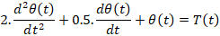
Writing the Torque Balance Equation

Substituting the values

So the differential equation that relates applied Torque and the angular displacement is
Question 1(b)

Taking Laplace Transform on both sides, assuming zero initial conditions

We have used the differentiation property of Laplace transform under zero initial conditions which states that
If

Then


So the differential equation in Laplace domain is
Question 1(c)


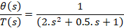
So the transfer function is

Add Answer to:
s) Given the following rotational mechanical system, hot relates the input variable T (applied torque) to...
Q2 A rotational mechanical system is shown in Figure 2.1. T(t) is the external torque and...
 Q2 A rotational mechanical system is shown in Figure 2.1. T(t) is the external torque and is the input to the system. 01(t) is the angular displacement of inertia Ji and O2(t) is the angular displacement of inertia J2. C and C are friction coefficients and K, and K2 are spring constants. (a) Draw the free-body diagrams for J; and Jz. (7 marks) (b) Derive the equations of motion for the system shown in Figure 2.1. (8 marks) (c) Using...
Question 3) Consider the mechanical system shown in figure, T(t) is the torque applied to shaft...
 Question 3) Consider the mechanical system shown in figure, T(t) is the torque applied to shaft 1 and z(t) is the rotation of shaft 2. J.Jz and Jz are the inertias of shafts 1,2 and 3 respectively, N,,N,N, and N, are the number of teeths of the gears,, D1, D, and D3 are the coefficient of viscous damping associated with shafts 1, 2 and 3 respectively, K is the spring constant of the torsional spring attached to shaft 3. Write...
θ2(s)/T(s) for the following rotational mechanical system Problem 4: Find the transfer function G(s) TO) N1...
 θ2(s)/T(s) for the following rotational mechanical system Problem 4: Find the transfer function G(s) TO) N1 = 4 Di 1 N-m-s/rad N2 121 kg-m2 N3-4 D2-2 N-m-s/rad K 64 N-m/rad- N4 16 D3 32 N-m-s/rad -16 kg-m2 000
Consider the rotational system with angular velocity "Ω(t)" and input torque "T(t)." TC From Newton's Law, the equation of motion is J Ω(t)-B. Ω(t) Now suppose that this input to...
 Consider the rotational system with angular velocity "Ω(t)" and input torque "T(t)." TC From Newton's Law, the equation of motion is J Ω(t)-B. Ω(t) Now suppose that this input torque is supplied by an electric motor Specifically, T(t) T(t) -Kamp Vin(t) where 1) "Vin is the input voltage supplied to the motor N-m 2) "Kamp" is the motor gain (this constant has units of Volt) So, the transfer function for this system is (s)Kamp The moment of inertia is known...
The mechanical system shown in the figure below is excited by a sinusoidal force f(t)-Fi cos(ut...
 The mechanical system shown in the figure below is excited by a sinusoidal force f(t)-Fi cos(ut + ?) N. The differential equation of the displacement x(t) is Use phasor techniques to solve for the displacement phasor Xin terms of the excitation frequency ? , and the mechanical elements M = 0.1 kg, D = 8 N-s/m , and K = 2,000 N/m . If Fi-10 N and ?? = 30°, determine the excitation frequency w (in rad/s) at which the...
PARTS: a-c Problem 1 (40 points) The rotational system shown in this diagram has a single...
 PARTS: a-c
Problem 1 (40 points) The rotational system shown in this diagram has a single torque input, T(t), and a single angular displacement output, (t). Also shown are the shaft polar moment of inertia, J, torsional spring constant, k, and rotational viscous damping coefficient, c. From the law of rotation (sum of the moments equal to polar moment of inertia times angular acceleration), we obtain: jä(t) + c)(t) + ko(t) = T(t). This ordinary differential equation is second-order, linear...
PARTS: a-c
Problem 1 (40 points) The rotational system shown in this diagram has a single torque input, T(t), and a single angular displacement output, (t). Also shown are the shaft polar moment of inertia, J, torsional spring constant, k, and rotational viscous damping coefficient, c. From the law of rotation (sum of the moments equal to polar moment of inertia times angular acceleration), we obtain: jä(t) + c)(t) + ko(t) = T(t). This ordinary differential equation is second-order, linear...
3.2 Pre-Lab Assignment When deriving the governing equations for an electromechanical system, it is often beneficial...
 3.2 Pre-Lab Assignment When deriving the governing equations for an electromechanical system, it is often beneficial to examine the electrical and mechanical components independently. Looking at only the electrical components of the QUBE-Servo DC motor (as shown in Figure 3.2): R v00 C e, (00 Figure 3.2: Electrical curcuit of the QUBE-Servo DC motor Q1. Write the differential equation in the form of Kirchoff's voltage law) in the Laplace domain for the electrical circuit (do not use parameter values given...
Question 3 Find the transfer function, G(s) s) / T(s), for the rotational mechanical system in...
 Question 3 Find the transfer function, G(s) s) / T(s), for the rotational mechanical system in Fig. Q3 below. The gears have inertia and bearing friction as shown. (20 marks) 3 Nm/rad 2 Nms/rad + 1 kg/m? N3 = 100 N2 = 100 T(t) N4 = 20 N = 20 0.04 Nms/rad Fig. Q3
Q5 The equation of the motion of the mechanical system shown in the following figure is...
 Q5 The equation of the motion of the mechanical system shown in the following figure is governed by the following differential equation d2 x dx m7+9+= -f(t) - 3kx dt2 dt where m, C and k are mass, damping coefficient and spring constant, respectively. Consider the system with m = 10 kg, c = 80 Ns/m, k = 50 N/m, and the system is at rest at time t = 0 s. f(t) is the external force acting on the...
please show steps For the system shown in the figure. a. Find the transfer function 0,(s)/T(S)....
 please show steps
For the system shown in the figure. a. Find the transfer function 0,(s)/T(S). b. Find the damping Dyo yield a 20% gvershoot in output angular displacement for a step torque input. N =25 kg-r W3 10 N2=5 D N-m/rad N4 5 0000
For the system shown in the figure. a. Find the transfer function 0,(s)/T(S). b. Find the damping Dyo yield a 20% gvershoot in output angular displacement for a step torque input. N =25 kg-r W3...
please show steps
For the system shown in the figure. a. Find the transfer function 0,(s)/T(S). b. Find the damping Dyo yield a 20% gvershoot in output angular displacement for a step torque input. N =25 kg-r W3 10 N2=5 D N-m/rad N4 5 0000
For the system shown in the figure. a. Find the transfer function 0,(s)/T(S). b. Find the damping Dyo yield a 20% gvershoot in output angular displacement for a step torque input. N =25 kg-r W3...
 Q2 A rotational mechanical system is shown in Figure 2.1. T(t) is the external torque and is the input to the system. 01(t) is the angular displacement of inertia Ji and O2(t) is the angular displacement of inertia J2. C and C are friction coefficients and K, and K2 are spring constants. (a) Draw the free-body diagrams for J; and Jz. (7 marks) (b) Derive the equations of motion for the system shown in Figure 2.1. (8 marks) (c) Using...
 Question 3) Consider the mechanical system shown in figure, T(t) is the torque applied to shaft 1 and z(t) is the rotation of shaft 2. J.Jz and Jz are the inertias of shafts 1,2 and 3 respectively, N,,N,N, and N, are the number of teeths of the gears,, D1, D, and D3 are the coefficient of viscous damping associated with shafts 1, 2 and 3 respectively, K is the spring constant of the torsional spring attached to shaft 3. Write...
 θ2(s)/T(s) for the following rotational mechanical system Problem 4: Find the transfer function G(s) TO) N1 = 4 Di 1 N-m-s/rad N2 121 kg-m2 N3-4 D2-2 N-m-s/rad K 64 N-m/rad- N4 16 D3 32 N-m-s/rad -16 kg-m2 000
 Consider the rotational system with angular velocity "Ω(t)" and input torque "T(t)." TC From Newton's Law, the equation of motion is J Ω(t)-B. Ω(t) Now suppose that this input torque is supplied by an electric motor Specifically, T(t) T(t) -Kamp Vin(t) where 1) "Vin is the input voltage supplied to the motor N-m 2) "Kamp" is the motor gain (this constant has units of Volt) So, the transfer function for this system is (s)Kamp The moment of inertia is known...
 The mechanical system shown in the figure below is excited by a sinusoidal force f(t)-Fi cos(ut + ?) N. The differential equation of the displacement x(t) is Use phasor techniques to solve for the displacement phasor Xin terms of the excitation frequency ? , and the mechanical elements M = 0.1 kg, D = 8 N-s/m , and K = 2,000 N/m . If Fi-10 N and ?? = 30°, determine the excitation frequency w (in rad/s) at which the...
 PARTS: a-c
Problem 1 (40 points) The rotational system shown in this diagram has a single torque input, T(t), and a single angular displacement output, (t). Also shown are the shaft polar moment of inertia, J, torsional spring constant, k, and rotational viscous damping coefficient, c. From the law of rotation (sum of the moments equal to polar moment of inertia times angular acceleration), we obtain: jä(t) + c)(t) + ko(t) = T(t). This ordinary differential equation is second-order, linear...
PARTS: a-c
Problem 1 (40 points) The rotational system shown in this diagram has a single torque input, T(t), and a single angular displacement output, (t). Also shown are the shaft polar moment of inertia, J, torsional spring constant, k, and rotational viscous damping coefficient, c. From the law of rotation (sum of the moments equal to polar moment of inertia times angular acceleration), we obtain: jä(t) + c)(t) + ko(t) = T(t). This ordinary differential equation is second-order, linear...
 3.2 Pre-Lab Assignment When deriving the governing equations for an electromechanical system, it is often beneficial to examine the electrical and mechanical components independently. Looking at only the electrical components of the QUBE-Servo DC motor (as shown in Figure 3.2): R v00 C e, (00 Figure 3.2: Electrical curcuit of the QUBE-Servo DC motor Q1. Write the differential equation in the form of Kirchoff's voltage law) in the Laplace domain for the electrical circuit (do not use parameter values given...
 Question 3 Find the transfer function, G(s) s) / T(s), for the rotational mechanical system in Fig. Q3 below. The gears have inertia and bearing friction as shown. (20 marks) 3 Nm/rad 2 Nms/rad + 1 kg/m? N3 = 100 N2 = 100 T(t) N4 = 20 N = 20 0.04 Nms/rad Fig. Q3
 Q5 The equation of the motion of the mechanical system shown in the following figure is governed by the following differential equation d2 x dx m7+9+= -f(t) - 3kx dt2 dt where m, C and k are mass, damping coefficient and spring constant, respectively. Consider the system with m = 10 kg, c = 80 Ns/m, k = 50 N/m, and the system is at rest at time t = 0 s. f(t) is the external force acting on the...
 please show steps
For the system shown in the figure. a. Find the transfer function 0,(s)/T(S). b. Find the damping Dyo yield a 20% gvershoot in output angular displacement for a step torque input. N =25 kg-r W3 10 N2=5 D N-m/rad N4 5 0000
For the system shown in the figure. a. Find the transfer function 0,(s)/T(S). b. Find the damping Dyo yield a 20% gvershoot in output angular displacement for a step torque input. N =25 kg-r W3...
please show steps
For the system shown in the figure. a. Find the transfer function 0,(s)/T(S). b. Find the damping Dyo yield a 20% gvershoot in output angular displacement for a step torque input. N =25 kg-r W3 10 N2=5 D N-m/rad N4 5 0000
For the system shown in the figure. a. Find the transfer function 0,(s)/T(S). b. Find the damping Dyo yield a 20% gvershoot in output angular displacement for a step torque input. N =25 kg-r W3...
Most questions answered within 3 hours.
-
Where is the error in this code sequence?
String s1 = "Hello";
String s2 = "ello";...
asked 10 months ago -
Financial data for Joel de Paris, Inc., for last year
follow:
Joel de Paris, Inc.
Balance...
asked 10 months ago -
Consider this reaction:
Al2(SO4)3 (aq)+ BaCl3
(aq) Al2Cl6 (aq)- +
3BaSO4(s) . What is the...
asked 10 months ago -
Suppose that Savneet is considering increasing her
recent random sample from 20 car rentals to 40...
asked 10 months ago -
Trucks arrive at an unloading terminal at an average rate of 120
per hour.
Trucks arrive...
asked 10 months ago -
Why are methanol and ethanol completely soluble in water while
octanol is not very little soluble....
asked 10 months ago -
A facilities manager at a university reads in a research report
that the mean amount of...
asked 10 months ago -
When the CuSO4 is rehydrated by adding water to the anhydrous
compound, is this an endothermic...
asked 10 months ago -
A ray of sunlight is passing from diamond into crown glass; the
angle of incidence is...
asked 10 months ago -
A block of mass 0.249 kg is placed on top of a light, vertical
spring of...
asked 10 months ago -
how do the kidneys compensate in the presences of acidosis
a) trigger hyperventilate
b) reserve acid...
asked 10 months ago -
Question 501 pts
The rental rate of capital to the firm increases. Which of the
following...
asked 10 months ago