
Use figure 5.25 to solve a, b, c.
Homework Answers
Add Answer to:
Use figure 5.25 to solve a, b, c.
Figure 5.25: Sequential Circuit. (a) Determine the circuit's...
sequential circuit analysis Sequential Circuit Analysis Consider the sequential circuit Derive the input equations B =...
 sequential circuit analysis
Sequential Circuit Analysis Consider the sequential circuit Derive the input equations B = D1 = Derive both forms of the State Table Draw the State Diagram
sequential circuit analysis
Sequential Circuit Analysis Consider the sequential circuit Derive the input equations B = D1 = Derive both forms of the State Table Draw the State Diagram
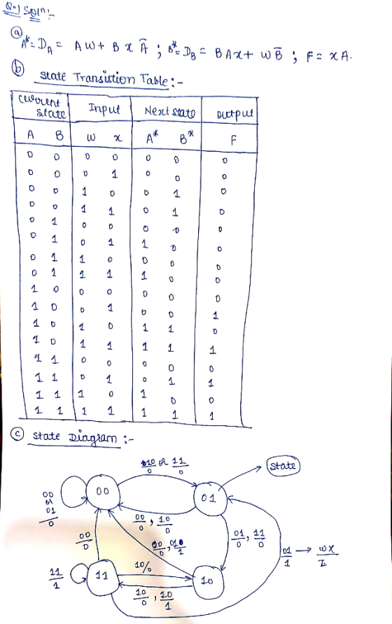
Design a sequential circuit with the following characteristic equations using T flip flop 1. A(t+1E A(t)B(t) +XA'(t) B(t+1) A'(t)B(t) + XB'(t) Draw the state Diagram for the circuit....
 Design a sequential circuit with the following characteristic equations using T flip flop 1. A(t+1E A(t)B(t) +XA'(t) B(t+1) A'(t)B(t) + XB'(t) Draw the state Diagram for the circuit.
Design a sequential circuit with the following characteristic equations using T flip flop 1. A(t+1E A(t)B(t) +XA'(t) B(t+1) A'(t)B(t) + XB'(t) Draw the state Diagram for the circuit.
Design a sequential circuit with the following characteristic equations using T flip flop 1. A(t+1E A(t)B(t) +XA'(t) B(t+1) A'(t)B(t) + XB'(t) Draw the state Diagram for the circuit.
03: 6 marks) Sequential circuit that has two flip-flops A and B and one input x...
 03: 6 marks) Sequential circuit that has two flip-flops A and B and one input x and a constant 'l'. It consists of a combinatorial logic connected to the JK flip-flops, as shown in Figure below. a. (2 marks) Derive the next state and output equations. b. (2 marks) Derive the state table of the sequential circuit. c. (2 marks) Draw the corresponding state diagram. K ā
Design a synchronous sequential counter circuit that has the state diagram shown in figure 1. Use...
 Design a synchronous sequential counter circuit that has the state diagram shown in figure 1. Use both D-type and T-type Flip Flops in your design. Show all your work in details. Extra credit will be given for implementation using other types of Flip Flops 3 4 Figure 1 Deliverables: 1. State Transition Table 2. K-Maps 3. Logical Expressions (Minimal Form) 4. Schematic Diagrams of the two designs 5. Verification steps for both designs.
Analyze the sequential counter circuit shown in figure 5.1. Derive the state transition table and diagram....
 Analyze the sequential counter
circuit shown in figure 5.1. Derive the state transition table and
diagram.
7400 U1 7400 01. 74x73 U2 4 74x13 76x73 Ly, QH122 7400 Reset (11) Clock - Figure 5.1
Analyze the sequential counter
circuit shown in figure 5.1. Derive the state transition table and
diagram.
7400 U1 7400 01. 74x73 U2 4 74x13 76x73 Ly, QH122 7400 Reset (11) Clock - Figure 5.1
1. A sequential circuit with two D flip-flops A and B, two inputs, x and y...
1. A sequential circuit with two D flip-flops A and B, two inputs, x and y ; and one output z is specified by the following next-state and output equations A(t + 1) = xy’ + xB B(t + 1) = xA + xB z = A (a) Draw the logic diagram of the circuit. (b) List the state table for the sequential circuit. (c) Draw the corresponding state diagram.
Q3) A sequential circuit with two D flip-flops A and B, two z is specified by...
 Q3) A sequential circuit with two D flip-flops A and B, two z is specified by the following next-state and output equations А(( + 1) — ху' + xB В(( + 1) %3 хА + xB' inputs, x and y; and one output z= A (a) Draw the logic diagram of the circuit (b) List the state table for the sequential circuit. (c) Draw the corresponding state diagram and indicate whether the circuit is Mealy or Мore Machinе.
2. (8 marks] Design a sequential circuit specified by the state diagram in the figure below,...
 2. (8 marks] Design a sequential circuit specified by the state diagram in the figure below, using D flip-flops. A. (4 marks] Construct the state table. B. [3 marks] Write the necessary equations using k-map. C. [1 mark] Implement the circuit. 01/0 ooo 0011 s, lovo 1010 10/0 oo! 10/ S2 01/o
2. A sequential circuit is given below. The states in the transition diagram are labeled AB, e.g., the state corresponding to the sequential circuit are X and Y, and its output is Z. Draw a complete...
 2. A sequential circuit is given below. The states in the transition diagram are labeled AB, e.g., the state corresponding to the sequential circuit are X and Y, and its output is Z. Draw a complete state transition diagram for the circuit. J. A
2. A sequential circuit is given below. The states in the transition diagram are labeled AB, e.g., the state corresponding to the sequential circuit are X and Y, and its output is Z. Draw a complete...
2. A sequential circuit is given below. The states in the transition diagram are labeled AB, e.g., the state corresponding to the sequential circuit are X and Y, and its output is Z. Draw a complete state transition diagram for the circuit. J. A
2. A sequential circuit is given below. The states in the transition diagram are labeled AB, e.g., the state corresponding to the sequential circuit are X and Y, and its output is Z. Draw a complete...
The sequential circuit shown below has two flip-flops A and B and one input x. It...
 The sequential circuit shown below has two flip-flops A and B and one input x. It consists of a combinatorial logic connected to the flip-flops, as shown in the Figure 1. Below. Analyze the sequential circuit below: A J A' K Q lo B 2-to-1 MUX Y J Q 11 S B K CLK Figure 1a. Sequential Circuit a) Derive the next state equations for the sequential circuit above: find expressions for JA and KA and Jb and KB as...
 sequential circuit analysis
Sequential Circuit Analysis Consider the sequential circuit Derive the input equations B = D1 = Derive both forms of the State Table Draw the State Diagram
sequential circuit analysis
Sequential Circuit Analysis Consider the sequential circuit Derive the input equations B = D1 = Derive both forms of the State Table Draw the State Diagram
 Design a sequential circuit with the following characteristic equations using T flip flop 1. A(t+1E A(t)B(t) +XA'(t) B(t+1) A'(t)B(t) + XB'(t) Draw the state Diagram for the circuit.
Design a sequential circuit with the following characteristic equations using T flip flop 1. A(t+1E A(t)B(t) +XA'(t) B(t+1) A'(t)B(t) + XB'(t) Draw the state Diagram for the circuit.
Design a sequential circuit with the following characteristic equations using T flip flop 1. A(t+1E A(t)B(t) +XA'(t) B(t+1) A'(t)B(t) + XB'(t) Draw the state Diagram for the circuit.
 03: 6 marks) Sequential circuit that has two flip-flops A and B and one input x and a constant 'l'. It consists of a combinatorial logic connected to the JK flip-flops, as shown in Figure below. a. (2 marks) Derive the next state and output equations. b. (2 marks) Derive the state table of the sequential circuit. c. (2 marks) Draw the corresponding state diagram. K ā
 Design a synchronous sequential counter circuit that has the state diagram shown in figure 1. Use both D-type and T-type Flip Flops in your design. Show all your work in details. Extra credit will be given for implementation using other types of Flip Flops 3 4 Figure 1 Deliverables: 1. State Transition Table 2. K-Maps 3. Logical Expressions (Minimal Form) 4. Schematic Diagrams of the two designs 5. Verification steps for both designs.
 Analyze the sequential counter
circuit shown in figure 5.1. Derive the state transition table and
diagram.
7400 U1 7400 01. 74x73 U2 4 74x13 76x73 Ly, QH122 7400 Reset (11) Clock - Figure 5.1
Analyze the sequential counter
circuit shown in figure 5.1. Derive the state transition table and
diagram.
7400 U1 7400 01. 74x73 U2 4 74x13 76x73 Ly, QH122 7400 Reset (11) Clock - Figure 5.1
 Q3) A sequential circuit with two D flip-flops A and B, two z is specified by the following next-state and output equations А(( + 1) — ху' + xB В(( + 1) %3 хА + xB' inputs, x and y; and one output z= A (a) Draw the logic diagram of the circuit (b) List the state table for the sequential circuit. (c) Draw the corresponding state diagram and indicate whether the circuit is Mealy or Мore Machinе.
 2. (8 marks] Design a sequential circuit specified by the state diagram in the figure below, using D flip-flops. A. (4 marks] Construct the state table. B. [3 marks] Write the necessary equations using k-map. C. [1 mark] Implement the circuit. 01/0 ooo 0011 s, lovo 1010 10/0 oo! 10/ S2 01/o
 2. A sequential circuit is given below. The states in the transition diagram are labeled AB, e.g., the state corresponding to the sequential circuit are X and Y, and its output is Z. Draw a complete state transition diagram for the circuit. J. A
2. A sequential circuit is given below. The states in the transition diagram are labeled AB, e.g., the state corresponding to the sequential circuit are X and Y, and its output is Z. Draw a complete...
2. A sequential circuit is given below. The states in the transition diagram are labeled AB, e.g., the state corresponding to the sequential circuit are X and Y, and its output is Z. Draw a complete state transition diagram for the circuit. J. A
2. A sequential circuit is given below. The states in the transition diagram are labeled AB, e.g., the state corresponding to the sequential circuit are X and Y, and its output is Z. Draw a complete...
 The sequential circuit shown below has two flip-flops A and B and one input x. It consists of a combinatorial logic connected to the flip-flops, as shown in the Figure 1. Below. Analyze the sequential circuit below: A J A' K Q lo B 2-to-1 MUX Y J Q 11 S B K CLK Figure 1a. Sequential Circuit a) Derive the next state equations for the sequential circuit above: find expressions for JA and KA and Jb and KB as...
Most questions answered within 3 hours.
-
Where is the error in this code sequence?
String s1 = "Hello";
String s2 = "ello";...
asked 10 months ago -
Financial data for Joel de Paris, Inc., for last year
follow:
Joel de Paris, Inc.
Balance...
asked 10 months ago -
Consider this reaction:
Al2(SO4)3 (aq)+ BaCl3
(aq) Al2Cl6 (aq)- +
3BaSO4(s) . What is the...
asked 10 months ago -
Suppose that Savneet is considering increasing her
recent random sample from 20 car rentals to 40...
asked 10 months ago -
Trucks arrive at an unloading terminal at an average rate of 120
per hour.
Trucks arrive...
asked 10 months ago -
Why are methanol and ethanol completely soluble in water while
octanol is not very little soluble....
asked 10 months ago -
A facilities manager at a university reads in a research report
that the mean amount of...
asked 10 months ago -
When the CuSO4 is rehydrated by adding water to the anhydrous
compound, is this an endothermic...
asked 10 months ago -
A ray of sunlight is passing from diamond into crown glass; the
angle of incidence is...
asked 10 months ago -
A block of mass 0.249 kg is placed on top of a light, vertical
spring of...
asked 10 months ago -
how do the kidneys compensate in the presences of acidosis
a) trigger hyperventilate
b) reserve acid...
asked 10 months ago -
Question 501 pts
The rental rate of capital to the firm increases. Which of the
following...
asked 10 months ago