
Homework Answers
Add Answer to:
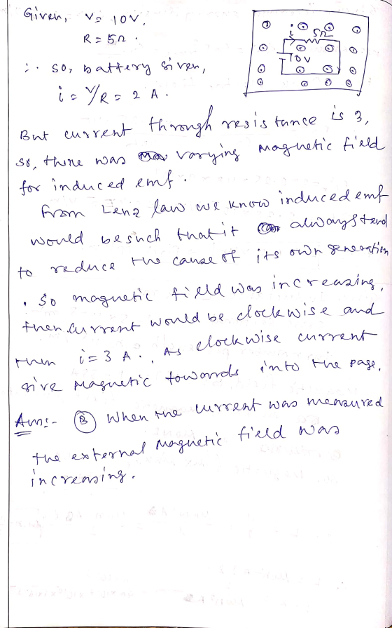
The circuit shown in the figure is located in an external magnetic field. At one point...
A loop is oriented in external magnetic field as shown in the picture. A magnetic field...
 A loop is oriented in external magnetic field as shown in the picture. A magnetic field suddenly vanishes. When viewed from north, what is the sense of the induced current in this loop as the field fades? N B W E S the induced current flows clockwise the induced current flows counterclockwise the current flows clockwise initially, and then it flows counterclockwise before stopping there is no induced current in this loop
In the figure, a region with constant (externally produced) magnetic field is shown. A wire loop...
 In the figure, a region with
constant (externally produced) magnetic field is shown. A wire loop
moves into the magnetic field.
//img.homeworklib.com/questions/b9da6130-ca78-11eb-8c71-8b0cea09251c.gif
Which of the following is correct? While the loop is moving into
the region with the constant external magnetic field, the magnetic
field inside the loop due to the induced current in the loop points
...
No magnetic field is induced by the movement of the loop.
... down
... left
... into the page
... right
......
In the figure, a region with
constant (externally produced) magnetic field is shown. A wire loop
moves into the magnetic field.
//img.homeworklib.com/questions/b9da6130-ca78-11eb-8c71-8b0cea09251c.gif
Which of the following is correct? While the loop is moving into
the region with the constant external magnetic field, the magnetic
field inside the loop due to the induced current in the loop points
...
No magnetic field is induced by the movement of the loop.
... down
... left
... into the page
... right
......
Help me figure it out plz Consider the wire below in an external, constant magnetic field...
 Help me figure it out plz
Consider the wire below in an external, constant magnetic field of 0.0100 T. The wire has an expanding radius given by r = r_0e^beta t where r_0 = 3.00 cm and beta = 0.250 s^-1. (a) What is the induced electric field in the wire at t = 2.00 s? (b) If the induced current is in the direction given below, what is the direction of the external magnetic field?
Help me figure it out plz
Consider the wire below in an external, constant magnetic field of 0.0100 T. The wire has an expanding radius given by r = r_0e^beta t where r_0 = 3.00 cm and beta = 0.250 s^-1. (a) What is the induced electric field in the wire at t = 2.00 s? (b) If the induced current is in the direction given below, what is the direction of the external magnetic field?
P.6-2 The circuit in Fig. 6-9 is situated in a magnetic field B a,3 cos (5?...
 P.6-2 The circuit in Fig. 6-9 is situated in a magnetic field B a,3 cos (5? 1071- ry) (pT). Assuming R -15(Q), find the current i P.6-4 In Fig. 6-10 assume a constant current i, - lo.but that the rectangular loop moves away with a constant velocity u = a,uo. Determine i2 when the loop is at a position as shown. FIGURE 69 A circuit in a time-varying magnetic FIGURE 6-10 A rectangular loop near a long field (Problem P.6-2)...
Current path shaped as shown in the figure produces a magnetic field of P, in the...
 Current path shaped as shown in the figure produces a magnetic field of P, in the center of the are. The arc makes an angle of 30.00 and the are's radius is 0.6m, find the magnitude and direction of the field produced at P, If current I is 3.0 A. re P*: 130.0° 0.600m
The circuit shown in the figure is used to make a magnetic balance to weigh objects....
 The circuit shown in the figure is used to make a magnetic
balance to weigh objects. The mass m to be measured is
hung from the center of the bar, that is in a uniform magnetic
field of 1.50 T, directed into the plane of the figure. The battery
voltage can be adjusted to vary the current in the circuit. The
horizontal bar is 60.0 cmlong and is made of extremely light-weight
material. It is connected to the battery by...
The circuit shown in the figure is used to make a magnetic
balance to weigh objects. The mass m to be measured is
hung from the center of the bar, that is in a uniform magnetic
field of 1.50 T, directed into the plane of the figure. The battery
voltage can be adjusted to vary the current in the circuit. The
horizontal bar is 60.0 cmlong and is made of extremely light-weight
material. It is connected to the battery by...
The circuit of (Figure 1) is a square 20 cm on a side. The magnetic field...
The circuit of (Figure 1) is a square 20 cm on a side. The magnetic field increases steadily from 0 T to 0.80 T in 11 ms . Figure1 of 1The figure shows a circuit in the magnetic field directed out of the page. The circuit is a square with a 20-ohm resistor in the upper side and the 9.0-volt battery in the left side. The battery has positive terminal at the top and negative terminal at the bottom. Part...
4. MAGNETIC FORCE II. (26 Marks) Magnetic Balance The circuit shown in Figure 1 is used...
 4. MAGNETIC FORCE II. (26 Marks) Magnetic Balance The circuit shown in Figure 1 is used to make a magnetic balance to weigh objects. The mass m to be measured is hung from the center of the bar that is in a magnetic field of 1.850 T as shown. The battery voltage can be adjusted to vary the current in the circuit. The horizontal bar is 65.000 сm long and is made of extremely light-weight material, (take it as massless)....
The lightbulb in the circuit shown in the figure(Figure 1) has a resistance of 14? and...
The lightbulb in the circuit shown in the figure(Figure 1) has a resistance of 14? and consumes 9.7W of power; the rod is 1.20m long and moves to the left with a constant speed. The strength of the magnetic field is 1.8T . find current in the circuit. (I) find speed of the rod (m/s)
A charged particle is moving in a uniform, constant magnetic field. Which one of the following...
 A charged particle is moving in a uniform, constant magnetic field. Which one of the following statements concerning the magnetic force exerted on the particle is false It does no work on the particle. It increases the speed of the particle. It changes the velocity of the particle. It can act only on a particle in motion. It does not change the kinetic energy of the particle. A circular current loop with radius of 0.100 m is located in the...
 A loop is oriented in external magnetic field as shown in the picture. A magnetic field suddenly vanishes. When viewed from north, what is the sense of the induced current in this loop as the field fades? N B W E S the induced current flows clockwise the induced current flows counterclockwise the current flows clockwise initially, and then it flows counterclockwise before stopping there is no induced current in this loop
 In the figure, a region with
constant (externally produced) magnetic field is shown. A wire loop
moves into the magnetic field.
//img.homeworklib.com/questions/b9da6130-ca78-11eb-8c71-8b0cea09251c.gif
Which of the following is correct? While the loop is moving into
the region with the constant external magnetic field, the magnetic
field inside the loop due to the induced current in the loop points
...
No magnetic field is induced by the movement of the loop.
... down
... left
... into the page
... right
......
In the figure, a region with
constant (externally produced) magnetic field is shown. A wire loop
moves into the magnetic field.
//img.homeworklib.com/questions/b9da6130-ca78-11eb-8c71-8b0cea09251c.gif
Which of the following is correct? While the loop is moving into
the region with the constant external magnetic field, the magnetic
field inside the loop due to the induced current in the loop points
...
No magnetic field is induced by the movement of the loop.
... down
... left
... into the page
... right
......
 Help me figure it out plz
Consider the wire below in an external, constant magnetic field of 0.0100 T. The wire has an expanding radius given by r = r_0e^beta t where r_0 = 3.00 cm and beta = 0.250 s^-1. (a) What is the induced electric field in the wire at t = 2.00 s? (b) If the induced current is in the direction given below, what is the direction of the external magnetic field?
Help me figure it out plz
Consider the wire below in an external, constant magnetic field of 0.0100 T. The wire has an expanding radius given by r = r_0e^beta t where r_0 = 3.00 cm and beta = 0.250 s^-1. (a) What is the induced electric field in the wire at t = 2.00 s? (b) If the induced current is in the direction given below, what is the direction of the external magnetic field?
 P.6-2 The circuit in Fig. 6-9 is situated in a magnetic field B a,3 cos (5? 1071- ry) (pT). Assuming R -15(Q), find the current i P.6-4 In Fig. 6-10 assume a constant current i, - lo.but that the rectangular loop moves away with a constant velocity u = a,uo. Determine i2 when the loop is at a position as shown. FIGURE 69 A circuit in a time-varying magnetic FIGURE 6-10 A rectangular loop near a long field (Problem P.6-2)...
 Current path shaped as shown in the figure produces a magnetic field of P, in the center of the are. The arc makes an angle of 30.00 and the are's radius is 0.6m, find the magnitude and direction of the field produced at P, If current I is 3.0 A. re P*: 130.0° 0.600m
 The circuit shown in the figure is used to make a magnetic
balance to weigh objects. The mass m to be measured is
hung from the center of the bar, that is in a uniform magnetic
field of 1.50 T, directed into the plane of the figure. The battery
voltage can be adjusted to vary the current in the circuit. The
horizontal bar is 60.0 cmlong and is made of extremely light-weight
material. It is connected to the battery by...
The circuit shown in the figure is used to make a magnetic
balance to weigh objects. The mass m to be measured is
hung from the center of the bar, that is in a uniform magnetic
field of 1.50 T, directed into the plane of the figure. The battery
voltage can be adjusted to vary the current in the circuit. The
horizontal bar is 60.0 cmlong and is made of extremely light-weight
material. It is connected to the battery by...
 4. MAGNETIC FORCE II. (26 Marks) Magnetic Balance The circuit shown in Figure 1 is used to make a magnetic balance to weigh objects. The mass m to be measured is hung from the center of the bar that is in a magnetic field of 1.850 T as shown. The battery voltage can be adjusted to vary the current in the circuit. The horizontal bar is 65.000 сm long and is made of extremely light-weight material, (take it as massless)....
 A charged particle is moving in a uniform, constant magnetic field. Which one of the following statements concerning the magnetic force exerted on the particle is false It does no work on the particle. It increases the speed of the particle. It changes the velocity of the particle. It can act only on a particle in motion. It does not change the kinetic energy of the particle. A circular current loop with radius of 0.100 m is located in the...
Most questions answered within 3 hours.
-
Where is the error in this code sequence?
String s1 = "Hello";
String s2 = "ello";...
asked 11 months ago -
Financial data for Joel de Paris, Inc., for last year
follow:
Joel de Paris, Inc.
Balance...
asked 11 months ago -
Consider this reaction:
Al2(SO4)3 (aq)+ BaCl3
(aq) Al2Cl6 (aq)- +
3BaSO4(s) . What is the...
asked 11 months ago -
Suppose that Savneet is considering increasing her
recent random sample from 20 car rentals to 40...
asked 11 months ago -
Trucks arrive at an unloading terminal at an average rate of 120
per hour.
Trucks arrive...
asked 11 months ago -
Why are methanol and ethanol completely soluble in water while
octanol is not very little soluble....
asked 11 months ago -
A facilities manager at a university reads in a research report
that the mean amount of...
asked 11 months ago -
When the CuSO4 is rehydrated by adding water to the anhydrous
compound, is this an endothermic...
asked 11 months ago -
A ray of sunlight is passing from diamond into crown glass; the
angle of incidence is...
asked 11 months ago -
A block of mass 0.249 kg is placed on top of a light, vertical
spring of...
asked 11 months ago -
how do the kidneys compensate in the presences of acidosis
a) trigger hyperventilate
b) reserve acid...
asked 11 months ago -
Question 501 pts
The rental rate of capital to the firm increases. Which of the
following...
asked 11 months ago