
Homework Answers
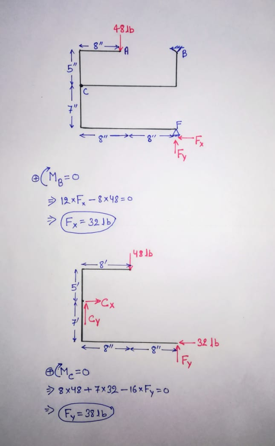
Correct obtion : ( e ) 33.5 lb

Add Answer to:
SII Sin OB 5. For the frame shown, the magnitude of the reaction at pin C...
A pin-connected frame is loaded as shown in the figure. a.) determine the reaction at C...
 A
pin-connected frame is loaded as shown in the figure.
a.) determine the reaction at C of the pin- connected
frame.
b.) determine the reaction at B of the pin- connected
frame.
c.) determine the shear force acting on section 2 (just to the
right of the 600 N load) of the pin-connected frame.
с 800 N 0.8 m ! 2 D B o 600 N 0.8 m 0.9 m 0.9 m A
A
pin-connected frame is loaded as shown in the figure.
a.) determine the reaction at C of the pin- connected
frame.
b.) determine the reaction at B of the pin- connected
frame.
c.) determine the shear force acting on section 2 (just to the
right of the 600 N load) of the pin-connected frame.
с 800 N 0.8 m ! 2 D B o 600 N 0.8 m 0.9 m 0.9 m A
Consider the gable frame shown in (Figure 1). Assume that A, B, and C are pin...
 Consider the gable frame shown in (Figure 1). Assume that A, B, and C are pin connections. The purlin loads such as D and E are applied perpendicular to the center line of each girder. Suppose that Fi = 400 lb, F2 = 600 lb, and F3 = 750 lb. Part A Determine the r and y components of the reaction at A. Express your answers using three significant figures separated by a comma. View Available Hint(s) IVO AQ 1...
Three bars are connected with frictionless pins to form the frame shown. The frame is loaded...
 Three bars are connected with frictionless pins to form the frame shown. The frame is loaded with a force of P-720 lb. The dimensions on te figure are a 5ft b-6.6ft, c-6.6ft d-5ft and e-12 ft. Determine the magnitude of (a) The resultant force in pin B (b) The horizontal and vertical components of force in pin D (c) The horizontal and vertical components of force in pin C (d) The horizontal and vertical components of force in pin A...
Three bars are connected with frictionless pins to form the frame shown. The frame is loaded...
 Three bars are connected with frictionless pins to form the frame shown. The frame is loaded with a force of P = 670 lb. The dimensions on th figure are a = 7 ft, b = 5.1 ft, C = 5.1 ft, d= 7 it, and e = 9.5 ft. Determine the magnitude of: (a) The resultant force in pin B. (b) The horizontal and vertical components of force in pin D. (c) The horizontal and vertical components of force...
The pin-connected frame shown consists of members ACE and BCD. It is loaded as shown. (Assume...
 The pin-connected frame shown consists of members ACE and BCD. It is loaded as shown. (Assume that the +x-axis is to the right and the+y-axis is up along submitted in WebAssign.) 6.0 m 6.0 m 8.0 m OD 1.70 KN.m 850 N in newte Determine the reaction components hinge B and pin C exert on member B magnitude N direction -Select- Ē, magnitude N direction -Select- Ex magnitude N direction -Select- č, magnitude N direction Select
The rigid frame shown below is supported by Pin A and Roller C.
 The rigid frame shown below is supported by Pin A and Roller C. [Point B is a rigid joint.] The frame supports a uniformly distributed load of 20 kN/m (downward) in Region BC, and a 250 kN point load (downward) located halfway between Pin A and rigid joint B. The modulus of elasticity of the entire frame is E = 200 GPa and the moment of inertia is I = 500 x 106 mm4. Determine the rotation (slope) at Joint...
Prob. #5: A coping saw is pictured below. The blade is tightened such that it is pulling gin the frame with a force of...
 Prob. #5: A coping saw is pictured below. The blade is tightened such that it is pulling gin the frame with a force of 50 lb 025 in 8 in Section a-a the saw frame at section a-a is 23. The magnitude of the internal normal force A)0 B) 25 D) 75 E) 200 C) 50 F) 400 24. The magnitude of the internal bending moment in the saw frame at section a-a is lb-in. A)C B) 50 C) 200...
1.2 m 0.1 m (5) In the frame shown, find the reaction forces at A and...
 1.2 m 0.1 m (5) In the frame shown, find the reaction forces at A and C, if the cylinder’s mass is 50 kg. i 0.3 m 0.6 m 50 lb/ft I 200 16.ft A B- 1 Q6) For the beam shown, draw the shear and moment diagrams and find the magnitude and location of the maximum moment. -20 ft -10 ft
#2) (35p.) Calculate the slopes "OB” and “Oc” in the frame shown in figure using “Slope-Deflection...
 #2) (35p.) Calculate the slopes "OB” and “Oc” in the frame shown in figure using “Slope-Deflection Equations”. Do not solve the system. Do not draw any diagram. (E: Constant). (“A” is the fixed type of support and “C” is the pin). 20 kN/m 20 kN/m D (I) B (1) 2m 30 KN (I) מר | 2m 5m X X X
 A
pin-connected frame is loaded as shown in the figure.
a.) determine the reaction at C of the pin- connected
frame.
b.) determine the reaction at B of the pin- connected
frame.
c.) determine the shear force acting on section 2 (just to the
right of the 600 N load) of the pin-connected frame.
с 800 N 0.8 m ! 2 D B o 600 N 0.8 m 0.9 m 0.9 m A
A
pin-connected frame is loaded as shown in the figure.
a.) determine the reaction at C of the pin- connected
frame.
b.) determine the reaction at B of the pin- connected
frame.
c.) determine the shear force acting on section 2 (just to the
right of the 600 N load) of the pin-connected frame.
с 800 N 0.8 m ! 2 D B o 600 N 0.8 m 0.9 m 0.9 m A
 Consider the gable frame shown in (Figure 1). Assume that A, B, and C are pin connections. The purlin loads such as D and E are applied perpendicular to the center line of each girder. Suppose that Fi = 400 lb, F2 = 600 lb, and F3 = 750 lb. Part A Determine the r and y components of the reaction at A. Express your answers using three significant figures separated by a comma. View Available Hint(s) IVO AQ 1...
 Three bars are connected with frictionless pins to form the frame shown. The frame is loaded with a force of P-720 lb. The dimensions on te figure are a 5ft b-6.6ft, c-6.6ft d-5ft and e-12 ft. Determine the magnitude of (a) The resultant force in pin B (b) The horizontal and vertical components of force in pin D (c) The horizontal and vertical components of force in pin C (d) The horizontal and vertical components of force in pin A...
 Three bars are connected with frictionless pins to form the frame shown. The frame is loaded with a force of P = 670 lb. The dimensions on th figure are a = 7 ft, b = 5.1 ft, C = 5.1 ft, d= 7 it, and e = 9.5 ft. Determine the magnitude of: (a) The resultant force in pin B. (b) The horizontal and vertical components of force in pin D. (c) The horizontal and vertical components of force...
 The pin-connected frame shown consists of members ACE and BCD. It is loaded as shown. (Assume that the +x-axis is to the right and the+y-axis is up along submitted in WebAssign.) 6.0 m 6.0 m 8.0 m OD 1.70 KN.m 850 N in newte Determine the reaction components hinge B and pin C exert on member B magnitude N direction -Select- Ē, magnitude N direction -Select- Ex magnitude N direction -Select- č, magnitude N direction Select
 Prob. #5: A coping saw is pictured below. The blade is tightened such that it is pulling gin the frame with a force of 50 lb 025 in 8 in Section a-a the saw frame at section a-a is 23. The magnitude of the internal normal force A)0 B) 25 D) 75 E) 200 C) 50 F) 400 24. The magnitude of the internal bending moment in the saw frame at section a-a is lb-in. A)C B) 50 C) 200...
 1.2 m 0.1 m (5) In the frame shown, find the reaction forces at A and C, if the cylinder’s mass is 50 kg. i 0.3 m 0.6 m 50 lb/ft I 200 16.ft A B- 1 Q6) For the beam shown, draw the shear and moment diagrams and find the magnitude and location of the maximum moment. -20 ft -10 ft
 #2) (35p.) Calculate the slopes "OB” and “Oc” in the frame shown in figure using “Slope-Deflection Equations”. Do not solve the system. Do not draw any diagram. (E: Constant). (“A” is the fixed type of support and “C” is the pin). 20 kN/m 20 kN/m D (I) B (1) 2m 30 KN (I) מר | 2m 5m X X X
 #2) (35p.) Calculate the slopes "OB” and “Oc” in the frame shown in figure using “Slope-Deflection Equations”. Do not solve the system. Do not draw any diagram. (E: Constant). (“A” is the fixed type of support and “C” is the pin). 20 kN/m 20 kN/m D (I) B (1) 2m 30 KN (I) מר | 2m 5m X X X
Most questions answered within 3 hours.
-
Where is the error in this code sequence?
String s1 = "Hello";
String s2 = "ello";...
asked 11 months ago -
Financial data for Joel de Paris, Inc., for last year
follow:
Joel de Paris, Inc.
Balance...
asked 11 months ago -
Consider this reaction:
Al2(SO4)3 (aq)+ BaCl3
(aq) Al2Cl6 (aq)- +
3BaSO4(s) . What is the...
asked 11 months ago -
Suppose that Savneet is considering increasing her
recent random sample from 20 car rentals to 40...
asked 11 months ago -
Trucks arrive at an unloading terminal at an average rate of 120
per hour.
Trucks arrive...
asked 11 months ago -
Why are methanol and ethanol completely soluble in water while
octanol is not very little soluble....
asked 11 months ago -
A facilities manager at a university reads in a research report
that the mean amount of...
asked 11 months ago -
When the CuSO4 is rehydrated by adding water to the anhydrous
compound, is this an endothermic...
asked 11 months ago -
A ray of sunlight is passing from diamond into crown glass; the
angle of incidence is...
asked 11 months ago -
A block of mass 0.249 kg is placed on top of a light, vertical
spring of...
asked 11 months ago -
how do the kidneys compensate in the presences of acidosis
a) trigger hyperventilate
b) reserve acid...
asked 11 months ago -
Question 501 pts
The rental rate of capital to the firm increases. Which of the
following...
asked 11 months ago