
Homework Answers
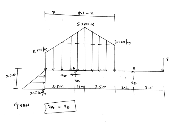

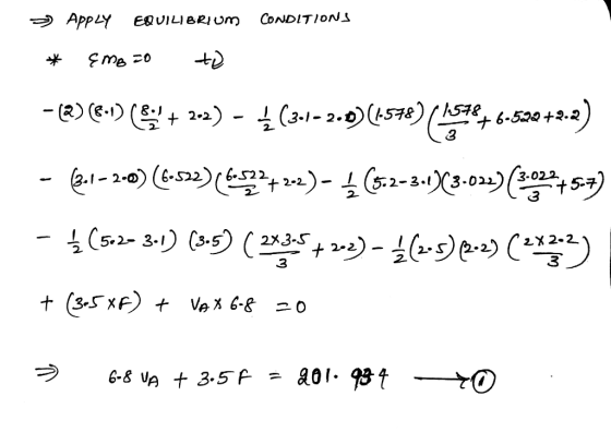
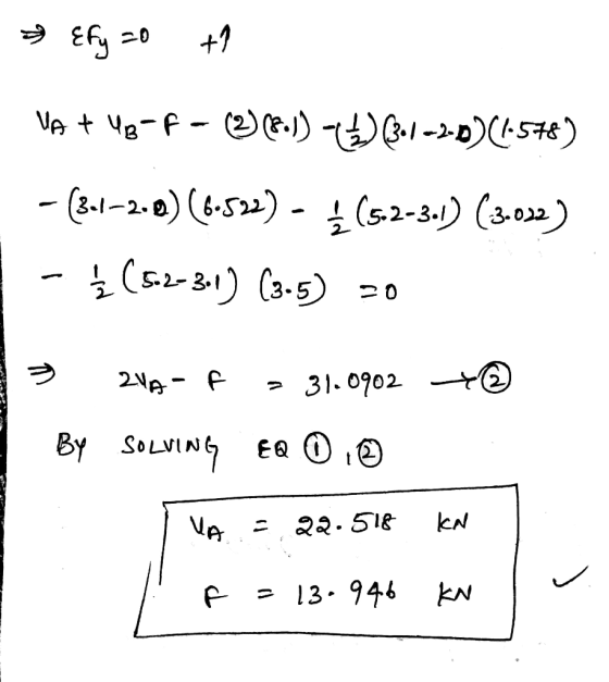
Add Answer to:
For the beam and loading shown, determine the magnitude of the force F for which the...
4. For the beam and loading shown, draw the shear force and bending moment diagrams and...
 4. For the beam and loading shown, draw the shear force and bending moment diagrams and determine the maximum bending and shear force and their locations. 20 KN 40 KN B D 250 mm |--2.5 m- 3m-4-2 m 80 mm 5. For the beam and loading shown, draw the shear force and bending moment diagrams and determine the maximum bending and shear force and their locations. 50 KN
Question AT For the beam and loading shown in Figure Al: - a. Determine the support...
 Question AT For the beam and loading shown in Figure Al: - a. Determine the support reactions b. Draw the shear and bending moment diagrams c. Determine the maximum absolute value of shear force and bending moment. 30 kN/m 60 kN C D K-2m-imta2m- Figure A1
For the beam shown below, determine (1) magnitude of the bending moment at the pin support...
 For the beam shown below, determine (1) magnitude of the bending
moment at the pin support A; and (2)the magnitude of shear force at
the immediate right side of the pin support A.
For the beam shown below, determine (1) magnitude of the bending moment at the pin support A; and (2) the magnitude of shear force at the immediate right side of the pin support A. 2 kN/m 1.5 kN 30° 1.2 m 0.6 1.2 m 1.8 m 1.2...
For the beam shown below, determine (1) magnitude of the bending
moment at the pin support A; and (2)the magnitude of shear force at
the immediate right side of the pin support A.
For the beam shown below, determine (1) magnitude of the bending moment at the pin support A; and (2) the magnitude of shear force at the immediate right side of the pin support A. 2 kN/m 1.5 kN 30° 1.2 m 0.6 1.2 m 1.8 m 1.2...
please explain in detail For the beam and loading shown, determine equations for the intemal shear...
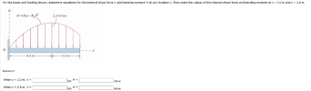 please explain in detail
For the beam and loading shown, determine equations for the intemal shear force V and bending moment M at any location x. Then state the values of the internal shear force and bending moment at x- 2.0 m and x-5.8 m. 2.3 kN/m 9 m 2.9 m Answers: When x- 2.0 m, v- kN KN-m When x- 5.8 m, V- M-
please explain in detail
For the beam and loading shown, determine equations for the intemal shear force V and bending moment M at any location x. Then state the values of the internal shear force and bending moment at x- 2.0 m and x-5.8 m. 2.3 kN/m 9 m 2.9 m Answers: When x- 2.0 m, v- kN KN-m When x- 5.8 m, V- M-
For the beam and loading shown (a) Determine the reactions at A. (b) Draw the shear...
 For the beam and loading shown (a) Determine the reactions at A. (b) Draw the shear and bending moment diagrams for the beam. 2 kN А c B 2 m 2 m 1 kN
For the beam and loading shown draw a shear and moment diagram then determine the minimum...
 For the beam and loading shown draw a shear and moment diagram
then determine the minimum required width b, knowing that for the
grade of timber used, the maximum allowable normal stress is 12 MPa
and the maximum allowable shear stress is 822 kPa. The dimensions
are the following: a = 148 mm, LAB = 0.9 m,
LBC = 1.1 m, LCE = 1.1 m, LED =
0.5 m, and the loading is PB = 2.3 kN, PC =
4.7...
For the beam and loading shown draw a shear and moment diagram
then determine the minimum required width b, knowing that for the
grade of timber used, the maximum allowable normal stress is 12 MPa
and the maximum allowable shear stress is 822 kPa. The dimensions
are the following: a = 148 mm, LAB = 0.9 m,
LBC = 1.1 m, LCE = 1.1 m, LED =
0.5 m, and the loading is PB = 2.3 kN, PC =
4.7...
2) A beam supports the loading shown below. Determine the internal normal force, shear force and...
 2) A beam supports the loading shown below. Determine the internal normal force, shear force and beading moment acting just to the left of point B and to the right of point Cof the 8 kN force. 8 KN loknom A D t 0 0 B C 5m
For the beam given below, determine the resultant internal loading acting on the cross section at...
 For the beam given below, determine the resultant internal loading acting on the cross section at C. Use the following assumption: The beam is weightless. Support A is a roller, and support B is a pin. The cross section C is 1 m away from A. (Tips: Internal loading includes normal force, shear force, and moment). . 100 kN 50 kN/m ol B 2m 1m 2m
Q5. The cantilever beam, AC, is subjected to the load case shown in Figure 5. For the loading shown, do the following: [10 Marks] a) Calculate the magnitude and direction of the reactions at A b) Usi...
 Q5. The cantilever beam, AC, is subjected to the load case shown in Figure 5. For the loading shown, do the following: [10 Marks] a) Calculate the magnitude and direction of the reactions at A b) Using the Macaulay function, determine the displacement in y of the point B of the beam (x 2.4 m from the support at A) [10 Marks] c) Determine the slope at B. [5 Marks] The beam has a Young's modulus of E-200 GPa and...
2) A beam supports the loading shown below. Determine the internal normal force, shear force and...
 2) A beam supports the loading shown below. Determine the internal normal force, shear force and beading moment acting just to the left of point B and to the right of point C of the 8 kN force. 8 KN loknom A D oo 6 ) B C 2m 5m 1
 4. For the beam and loading shown, draw the shear force and bending moment diagrams and determine the maximum bending and shear force and their locations. 20 KN 40 KN B D 250 mm |--2.5 m- 3m-4-2 m 80 mm 5. For the beam and loading shown, draw the shear force and bending moment diagrams and determine the maximum bending and shear force and their locations. 50 KN
 Question AT For the beam and loading shown in Figure Al: - a. Determine the support reactions b. Draw the shear and bending moment diagrams c. Determine the maximum absolute value of shear force and bending moment. 30 kN/m 60 kN C D K-2m-imta2m- Figure A1
 For the beam shown below, determine (1) magnitude of the bending
moment at the pin support A; and (2)the magnitude of shear force at
the immediate right side of the pin support A.
For the beam shown below, determine (1) magnitude of the bending moment at the pin support A; and (2) the magnitude of shear force at the immediate right side of the pin support A. 2 kN/m 1.5 kN 30° 1.2 m 0.6 1.2 m 1.8 m 1.2...
For the beam shown below, determine (1) magnitude of the bending
moment at the pin support A; and (2)the magnitude of shear force at
the immediate right side of the pin support A.
For the beam shown below, determine (1) magnitude of the bending moment at the pin support A; and (2) the magnitude of shear force at the immediate right side of the pin support A. 2 kN/m 1.5 kN 30° 1.2 m 0.6 1.2 m 1.8 m 1.2...
 please explain in detail
For the beam and loading shown, determine equations for the intemal shear force V and bending moment M at any location x. Then state the values of the internal shear force and bending moment at x- 2.0 m and x-5.8 m. 2.3 kN/m 9 m 2.9 m Answers: When x- 2.0 m, v- kN KN-m When x- 5.8 m, V- M-
please explain in detail
For the beam and loading shown, determine equations for the intemal shear force V and bending moment M at any location x. Then state the values of the internal shear force and bending moment at x- 2.0 m and x-5.8 m. 2.3 kN/m 9 m 2.9 m Answers: When x- 2.0 m, v- kN KN-m When x- 5.8 m, V- M-
 For the beam and loading shown (a) Determine the reactions at A. (b) Draw the shear and bending moment diagrams for the beam. 2 kN А c B 2 m 2 m 1 kN
 For the beam and loading shown draw a shear and moment diagram
then determine the minimum required width b, knowing that for the
grade of timber used, the maximum allowable normal stress is 12 MPa
and the maximum allowable shear stress is 822 kPa. The dimensions
are the following: a = 148 mm, LAB = 0.9 m,
LBC = 1.1 m, LCE = 1.1 m, LED =
0.5 m, and the loading is PB = 2.3 kN, PC =
4.7...
For the beam and loading shown draw a shear and moment diagram
then determine the minimum required width b, knowing that for the
grade of timber used, the maximum allowable normal stress is 12 MPa
and the maximum allowable shear stress is 822 kPa. The dimensions
are the following: a = 148 mm, LAB = 0.9 m,
LBC = 1.1 m, LCE = 1.1 m, LED =
0.5 m, and the loading is PB = 2.3 kN, PC =
4.7...
 2) A beam supports the loading shown below. Determine the internal normal force, shear force and beading moment acting just to the left of point B and to the right of point Cof the 8 kN force. 8 KN loknom A D t 0 0 B C 5m
 For the beam given below, determine the resultant internal loading acting on the cross section at C. Use the following assumption: The beam is weightless. Support A is a roller, and support B is a pin. The cross section C is 1 m away from A. (Tips: Internal loading includes normal force, shear force, and moment). . 100 kN 50 kN/m ol B 2m 1m 2m
 Q5. The cantilever beam, AC, is subjected to the load case shown in Figure 5. For the loading shown, do the following: [10 Marks] a) Calculate the magnitude and direction of the reactions at A b) Using the Macaulay function, determine the displacement in y of the point B of the beam (x 2.4 m from the support at A) [10 Marks] c) Determine the slope at B. [5 Marks] The beam has a Young's modulus of E-200 GPa and...
 2) A beam supports the loading shown below. Determine the internal normal force, shear force and beading moment acting just to the left of point B and to the right of point C of the 8 kN force. 8 KN loknom A D oo 6 ) B C 2m 5m 1
Most questions answered within 3 hours.
-
Where is the error in this code sequence?
String s1 = "Hello";
String s2 = "ello";...
asked 11 months ago -
Financial data for Joel de Paris, Inc., for last year
follow:
Joel de Paris, Inc.
Balance...
asked 11 months ago -
Consider this reaction:
Al2(SO4)3 (aq)+ BaCl3
(aq) Al2Cl6 (aq)- +
3BaSO4(s) . What is the...
asked 11 months ago -
Suppose that Savneet is considering increasing her
recent random sample from 20 car rentals to 40...
asked 11 months ago -
Trucks arrive at an unloading terminal at an average rate of 120
per hour.
Trucks arrive...
asked 11 months ago -
Why are methanol and ethanol completely soluble in water while
octanol is not very little soluble....
asked 11 months ago -
A facilities manager at a university reads in a research report
that the mean amount of...
asked 11 months ago -
When the CuSO4 is rehydrated by adding water to the anhydrous
compound, is this an endothermic...
asked 11 months ago -
A ray of sunlight is passing from diamond into crown glass; the
angle of incidence is...
asked 11 months ago -
A block of mass 0.249 kg is placed on top of a light, vertical
spring of...
asked 11 months ago -
how do the kidneys compensate in the presences of acidosis
a) trigger hyperventilate
b) reserve acid...
asked 11 months ago -
Question 501 pts
The rental rate of capital to the firm increases. Which of the
following...
asked 11 months ago