
Homework Answers
Explanation:
Area enclosed by wall midline is given by AE= 1/2(bxh)
=
=45000mm2
a)The shear flow distribution
Since the Torque acts at the exact middle of the cross section,

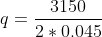
=35000 Ns/m
b) The maximum shear stress,
Since the Torque acts at the exact middle of the cross section, and thickness of the wall is constant throughout the section,


Maximum shear stress  25.926
Mpa.
25.926
Mpa.
c) Rate of twist
Angle of twist is given by,


T=3150 Nm
G=27.5 Gpa
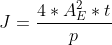
P(perimeter)=406.97+427.2+225
=1059.17 mm
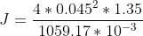
J= 1.0324 x 10⁻⁵ m4

=0.01109 rad/m.
Add Answer to:
Question 2 The single-cell thin-walled beam of Figure 2 with all dimensions in mm has a...
The cross-section of a thin walled single cell tube is shown in Figure 1 below. The...
 The cross-section of a thin walled single cell tube is shown in Figure 1 below. The tube supports a torque of T-3 kN.m over a length of 8 m. Consider G of the material as 79 GPa. 1. Determine the shear stresses in the walls and angle of twist 2. A vertical web of wall thickness of 2mm is added in the single cell to make it a two cell tube shown in Figure 2 below. Also determine the shear...
5.4. A thin walled box section has two compart- ments as shown in Figure 5.26. The...
 5.4. A thin walled box section has two compart- ments as shown in Figure 5.26. The thickness of the section is constant. What is the shear stress in both the cells? Take a10 cm,8 mm. What will be the angular twist per unit length if G= 80 kN/mm"? Torque applied on shaft is 400 Nm. a Figure 5.26 Problem 5.4
3- Determine the maximum shear stress in the beam section shown in the figure. Determine also...
 3- Determine the maximum shear stress in the beam section shown in the figure. Determine also the rate of twist of the beam section if the shear modulus G is 25 GPa. 100 mm T-25 N.m 3 mm 3 mm 50 mm 80 mm 2 mm
3- Determine the maximum shear stress in the beam section shown in the figure. Determine also the rate of twist of the beam section if the shear modulus G is 25 GPa. 100 mm...
3- Determine the maximum shear stress in the beam section shown in the figure. Determine also the rate of twist of the beam section if the shear modulus G is 25 GPa. 100 mm T-25 N.m 3 mm 3 mm 50 mm 80 mm 2 mm
3- Determine the maximum shear stress in the beam section shown in the figure. Determine also the rate of twist of the beam section if the shear modulus G is 25 GPa. 100 mm...
The hollow thin-walled hollow section of aluminium alloy illustrated below is 1200 mm long. It has one free end and the...
 The hollow thin-walled hollow section of aluminium alloy
illustrated below is 1200 mm long. It has one free end and the
other is built into a solid wall. At the free end, the following
loads are applied in the directions illustrated and distributed
evenly over the perimeter of the section:- A central, axial
compressive load, P = 10 kN; and A torque, T = 0.2 kN.m. Properties
of the aluminium alloy are given as E = 72 GPa and =...
The hollow thin-walled hollow section of aluminium alloy
illustrated below is 1200 mm long. It has one free end and the
other is built into a solid wall. At the free end, the following
loads are applied in the directions illustrated and distributed
evenly over the perimeter of the section:- A central, axial
compressive load, P = 10 kN; and A torque, T = 0.2 kN.m. Properties
of the aluminium alloy are given as E = 72 GPa and =...
Question 2: Torsion (30 marks) An aluminium alloy section illustrated in Figure 2 (dimensions in mm)...
 Question 2: Torsion (30 marks)
An aluminium alloy section illustrated in Figure 2 (dimensions
in mm) is subjected to a torsion load of 340 N.m. The length of the
section that carries this torsion load is 2.2 m, and the modulus of
rigidity for the aluminium is 27 GPa.
(a) Determine the maximum shear stress in the section. [15
marks]
(b) Calculate the angle of twist (expressed in degrees). [15
marks]
42.0 30.0 25.0 Figure 2. Section of torsion member...
Question 2: Torsion (30 marks)
An aluminium alloy section illustrated in Figure 2 (dimensions
in mm) is subjected to a torsion load of 340 N.m. The length of the
section that carries this torsion load is 2.2 m, and the modulus of
rigidity for the aluminium is 27 GPa.
(a) Determine the maximum shear stress in the section. [15
marks]
(b) Calculate the angle of twist (expressed in degrees). [15
marks]
42.0 30.0 25.0 Figure 2. Section of torsion member...
(2) The shaft is made from a solid steel section AB and a tubular portion made...
 (2) The shaft is made from a solid steel section AB and a tubular portion made of steel and having a brass core. If it is fixed to a rigid support at A, and a torque of T= 50 N.m is applied to it at C, determine the angle of twist that occurs at C and compute the maximum shear stress and maximum shear strain in the brass and steel. Take Gsi = 75 GPa, Ghr = 37.5 GPa. 800...
An I-section has the dimensions shown in Fig. Q4 and is subjected to an axial torque,...
 An I-section has the dimensions shown in Fig. Q4 and is subjected to an axial torque, T = 5000 Nm A) Determine the maximum value of the shear stress (Tmax) in the material. (8 marks) B) Find the twist angle per meter length, (0/L). Assume the modulus of rigidity G for the material is 82 GN/m2. d1= 266 mm — b1 = 30 b2= 16.5 mm d2= 779 mm b3 = 30 Fig. Q4: An I-Section Structure.
Problem #2 (20 points): A 3m long aluminum tube (G = 27 GPa) has the cross...
 Problem #2 (20 points): A 3m long aluminum tube (G = 27 GPa) has the cross section shown be N.m torque is applied to the tube, find the average shear stress at points a and b, and total angle or that the dimensions given are to the outer edge. S the cross section shown below. If a 100 points a and b, and total angle of twist. Note 2 mm 4 mm- 40 mm 55 mm 4 mm 55 mm
A thin-walled beam has the cross-section shown in the figure below. If the beam is subjected...
 A thin-walled beam has the cross-section shown in the figure
below. If the beam is subjected to a bending moment Mx
in the plane of the web 23:
Prob. 2 A thin-walled beam has the cross-section shown in the figure below. If the beam is subjected to a bending moment M in the plane of the web 23: h2 2t 2t 2h 1. 2. Find the section properties Find the direct stress distribution equation in the beam cross-section (15 pts)...
A thin-walled beam has the cross-section shown in the figure
below. If the beam is subjected to a bending moment Mx
in the plane of the web 23:
Prob. 2 A thin-walled beam has the cross-section shown in the figure below. If the beam is subjected to a bending moment M in the plane of the web 23: h2 2t 2t 2h 1. 2. Find the section properties Find the direct stress distribution equation in the beam cross-section (15 pts)...
75 mm 1.5 m T = 48 N·m 2 m 150 mm Two solid steel 20-mm-diameter...
 75 mm 1.5 m T = 48 N·m 2 m 150 mm Two solid steel 20-mm-diameter shafts are coupled together using the perfectly meshed gears shown. Shaft DC is fixed to the wall at D and supported with a frictionless journal bearing. Shaft EF is supported with two frictionless journal bearings. The modulus of rigidity of steel is 80 GPa. Before the torque is applied, the angle of twist in each shaft is zero, and the angle of rotation of...
 The cross-section of a thin walled single cell tube is shown in Figure 1 below. The tube supports a torque of T-3 kN.m over a length of 8 m. Consider G of the material as 79 GPa. 1. Determine the shear stresses in the walls and angle of twist 2. A vertical web of wall thickness of 2mm is added in the single cell to make it a two cell tube shown in Figure 2 below. Also determine the shear...
 5.4. A thin walled box section has two compart- ments as shown in Figure 5.26. The thickness of the section is constant. What is the shear stress in both the cells? Take a10 cm,8 mm. What will be the angular twist per unit length if G= 80 kN/mm"? Torque applied on shaft is 400 Nm. a Figure 5.26 Problem 5.4
 3- Determine the maximum shear stress in the beam section shown in the figure. Determine also the rate of twist of the beam section if the shear modulus G is 25 GPa. 100 mm T-25 N.m 3 mm 3 mm 50 mm 80 mm 2 mm
3- Determine the maximum shear stress in the beam section shown in the figure. Determine also the rate of twist of the beam section if the shear modulus G is 25 GPa. 100 mm...
3- Determine the maximum shear stress in the beam section shown in the figure. Determine also the rate of twist of the beam section if the shear modulus G is 25 GPa. 100 mm T-25 N.m 3 mm 3 mm 50 mm 80 mm 2 mm
3- Determine the maximum shear stress in the beam section shown in the figure. Determine also the rate of twist of the beam section if the shear modulus G is 25 GPa. 100 mm...
 The hollow thin-walled hollow section of aluminium alloy
illustrated below is 1200 mm long. It has one free end and the
other is built into a solid wall. At the free end, the following
loads are applied in the directions illustrated and distributed
evenly over the perimeter of the section:- A central, axial
compressive load, P = 10 kN; and A torque, T = 0.2 kN.m. Properties
of the aluminium alloy are given as E = 72 GPa and =...
The hollow thin-walled hollow section of aluminium alloy
illustrated below is 1200 mm long. It has one free end and the
other is built into a solid wall. At the free end, the following
loads are applied in the directions illustrated and distributed
evenly over the perimeter of the section:- A central, axial
compressive load, P = 10 kN; and A torque, T = 0.2 kN.m. Properties
of the aluminium alloy are given as E = 72 GPa and =...
 Question 2: Torsion (30 marks)
An aluminium alloy section illustrated in Figure 2 (dimensions
in mm) is subjected to a torsion load of 340 N.m. The length of the
section that carries this torsion load is 2.2 m, and the modulus of
rigidity for the aluminium is 27 GPa.
(a) Determine the maximum shear stress in the section. [15
marks]
(b) Calculate the angle of twist (expressed in degrees). [15
marks]
42.0 30.0 25.0 Figure 2. Section of torsion member...
Question 2: Torsion (30 marks)
An aluminium alloy section illustrated in Figure 2 (dimensions
in mm) is subjected to a torsion load of 340 N.m. The length of the
section that carries this torsion load is 2.2 m, and the modulus of
rigidity for the aluminium is 27 GPa.
(a) Determine the maximum shear stress in the section. [15
marks]
(b) Calculate the angle of twist (expressed in degrees). [15
marks]
42.0 30.0 25.0 Figure 2. Section of torsion member...
 (2) The shaft is made from a solid steel section AB and a tubular portion made of steel and having a brass core. If it is fixed to a rigid support at A, and a torque of T= 50 N.m is applied to it at C, determine the angle of twist that occurs at C and compute the maximum shear stress and maximum shear strain in the brass and steel. Take Gsi = 75 GPa, Ghr = 37.5 GPa. 800...
 An I-section has the dimensions shown in Fig. Q4 and is subjected to an axial torque, T = 5000 Nm A) Determine the maximum value of the shear stress (Tmax) in the material. (8 marks) B) Find the twist angle per meter length, (0/L). Assume the modulus of rigidity G for the material is 82 GN/m2. d1= 266 mm — b1 = 30 b2= 16.5 mm d2= 779 mm b3 = 30 Fig. Q4: An I-Section Structure.
 Problem #2 (20 points): A 3m long aluminum tube (G = 27 GPa) has the cross section shown be N.m torque is applied to the tube, find the average shear stress at points a and b, and total angle or that the dimensions given are to the outer edge. S the cross section shown below. If a 100 points a and b, and total angle of twist. Note 2 mm 4 mm- 40 mm 55 mm 4 mm 55 mm
 A thin-walled beam has the cross-section shown in the figure
below. If the beam is subjected to a bending moment Mx
in the plane of the web 23:
Prob. 2 A thin-walled beam has the cross-section shown in the figure below. If the beam is subjected to a bending moment M in the plane of the web 23: h2 2t 2t 2h 1. 2. Find the section properties Find the direct stress distribution equation in the beam cross-section (15 pts)...
A thin-walled beam has the cross-section shown in the figure
below. If the beam is subjected to a bending moment Mx
in the plane of the web 23:
Prob. 2 A thin-walled beam has the cross-section shown in the figure below. If the beam is subjected to a bending moment M in the plane of the web 23: h2 2t 2t 2h 1. 2. Find the section properties Find the direct stress distribution equation in the beam cross-section (15 pts)...
 75 mm 1.5 m T = 48 N·m 2 m 150 mm Two solid steel 20-mm-diameter shafts are coupled together using the perfectly meshed gears shown. Shaft DC is fixed to the wall at D and supported with a frictionless journal bearing. Shaft EF is supported with two frictionless journal bearings. The modulus of rigidity of steel is 80 GPa. Before the torque is applied, the angle of twist in each shaft is zero, and the angle of rotation of...
Most questions answered within 3 hours.
-
Where is the error in this code sequence?
String s1 = "Hello";
String s2 = "ello";...
asked 11 months ago -
Financial data for Joel de Paris, Inc., for last year
follow:
Joel de Paris, Inc.
Balance...
asked 11 months ago -
Consider this reaction:
Al2(SO4)3 (aq)+ BaCl3
(aq) Al2Cl6 (aq)- +
3BaSO4(s) . What is the...
asked 11 months ago -
Suppose that Savneet is considering increasing her
recent random sample from 20 car rentals to 40...
asked 11 months ago -
Trucks arrive at an unloading terminal at an average rate of 120
per hour.
Trucks arrive...
asked 11 months ago -
Why are methanol and ethanol completely soluble in water while
octanol is not very little soluble....
asked 11 months ago -
A facilities manager at a university reads in a research report
that the mean amount of...
asked 11 months ago -
When the CuSO4 is rehydrated by adding water to the anhydrous
compound, is this an endothermic...
asked 11 months ago -
A ray of sunlight is passing from diamond into crown glass; the
angle of incidence is...
asked 11 months ago -
A block of mass 0.249 kg is placed on top of a light, vertical
spring of...
asked 11 months ago -
how do the kidneys compensate in the presences of acidosis
a) trigger hyperventilate
b) reserve acid...
asked 11 months ago -
Question 501 pts
The rental rate of capital to the firm increases. Which of the
following...
asked 11 months ago