
Homework Answers
There is little sign mistake in the question.either at the
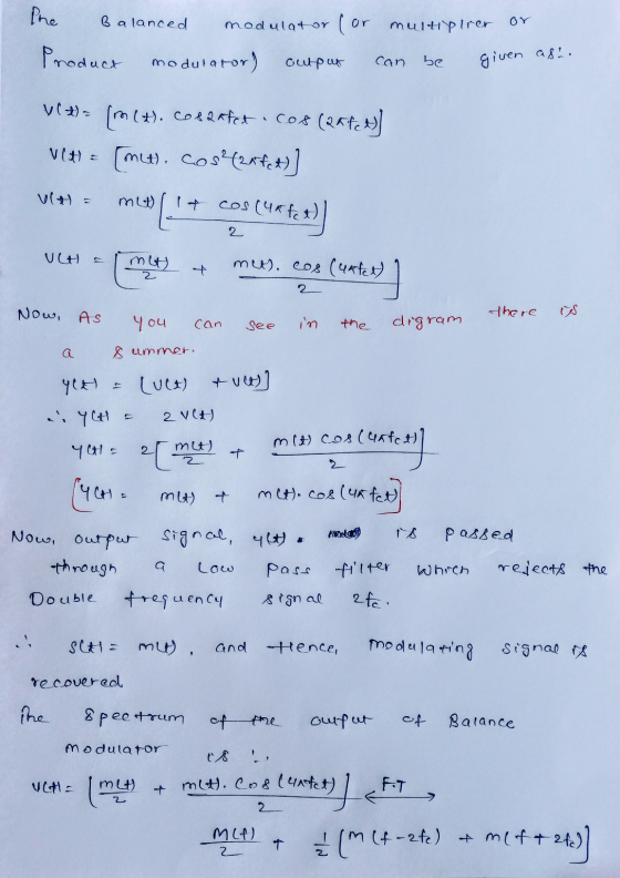
summer both the previous output must be adding in nature.other wise
they will cancel each other and nothing is obtained . Hence I
assume that both the. Previous output are adding.

Add Answer to:
3. Show that the circuit below can be used as a DSB demodulator. Specify the properties...
(2) Find the output of the DSB-SC demodulator shown in Fig.Q2 below, if the local oscillator...
 (2) Find the output of the DSB-SC demodulator shown in Fig.Q2 below, if the local oscillator at the receiver has a phase difference of $ . Also find the power of the signal v,(t) Product modulator (mixer) DSB-SC Modulated Signal vít) Low-Pass Filter Demodulated Signal v.(t) s(t)= m(t)4, cos(21f1) cos (21 f1+0) Local Oscillator Fig. 22
AM Modulator AM Demodulator m(t) SAM-DSB-Sc(t) mdemod(t) LPF cos2nfct cos2nfct Figure 1 P1. For the system...
 AM Modulator AM Demodulator m(t) SAM-DSB-Sc(t) mdemod(t) LPF cos2nfct cos2nfct Figure 1 P1. For the system shown in Figure 1, sketch the signals m(t), SAM-DSB-sc(t), and mde mod(t) in the time and frequency domain, assuming m(t)=cos 20ra and that AM- DSB-SC is the modulation scheme used with f. = 100Hz
AM Modulator AM Demodulator m(t) SAM-DSB-Sc(t) mdemod(t) LPF cos2nfct cos2nfct Figure 1 P1. For the system...
 AM Modulator AM Demodulator m(t) SAM-DSB-Sc(t) mdemod(t) LPF cos2nfct cos2nfct Figure 1 P1. For the system shown in Figure 1, sketch the signals m(t), SAM-DSB-sc(t), and mde mod (t) in the time and frequency domain, assuming m(t)=cos 20rd and that AM- DSB-SC is the modulation scheme used with f. = 100Hz P2. Repeat P1 changing m(t) to a 10 Hz square wave, with amplitude 1 (Figure 2) s(t) t 0.05 0.1 Figure 2
AM Modulator AM Demodulator m(t) mdemod(t) SAM-DSB-C(t) LPF Х Х с cos21fct cos2nfct Figure 3 P3....
 AM Modulator AM Demodulator m(t) mdemod(t) SAM-DSB-C(t) LPF Х Х с cos21fct cos2nfct Figure 3 P3. For the system shown in Figure 3, sketch the signals m(t), SAM-DSP-c(t), and mde mod(t) in the time and frequency domain, assuming m(t)=cos 20rd and that AM- DSB-C is the modulation scheme used with f. = 100Hz. Use DC offset c=1. P4. Repeat P3 changing m(t) to a 10 Hz square wave, with amplitude 1 (Figure 2). P5. Repeat P3 and P4, using DC...
[15 points] You are asked to design a DSB-SC AM modulator to generate a modulated signal km(t)cos...
 [15 points] You are asked to design a DSB-SC AM modulator to generate a modulated signal km(t)cos(wt+0), where m(t) is a signal band-limited to B Hz. The following figure shows a DSB- SC AM modulator available in the stockroom. The carrier generator available generates not cos(wct), but cos (wct). Explain whether you would be able to generate the desired signal using only this equipment. You may use any kind of filter you like. 3. What kind of filter is required...
The following non-coherent demodulator is used to demodulate an AM signal given by XAM(t) = [A+m(t)]...
 The following non-coherent demodulator is used to demodulate an AM signal given by XAM(t) = [A+m(t)] cos(2? f t). Find the output of the demodulator, mo(t). Mote that the squaring device simply squares the incoming signal. What do you think can be done to obtain the message signal from the output signal? XDsB.sc(t) Squaring device Low pass Filter mo(t)
Exercise 7: R t Envelope Detector y(0 The circuit in the figure above is a good approximation to ...
 Exercise 7: R t Envelope Detector y(0 The circuit in the figure above is a good approximation to an ideal differentiator demodulator if С 0.1 h, where fe is the carrier frequency of the FM signal and fr is the cut-off frequency of the RC high-pass filter. The input FM signal is given by the following. DrM(t) 4 cos[10 nt + 10 T (5 sin(10 mt))] a) b) Specify the value of the resistance R such that fe-0.1 h, when...
LPF Show how the Fing modulator ean be (used as a demodulator for DSBSC-AM if the...
 LPF Show how the Fing modulator ean be (used as a demodulator for DSBSC-AM if the input signal ist-o-s@ cos(2z/ 1). the input signal iss (0) st)cos(2nf) (2 points)
can you please solve this problem step by step, thank you!! 1. Consider a DSB-SC signal...
 can you please solve this problem step by step, thank
you!!
1. Consider a DSB-SC signal with noise passes through a demodulator shown below. ViC0) 2(0) но но 0) The input signal plus noise is v,(t)-5,() + n'(t) where 5,0): Am(1)cos2r/rt, m(1) cos 2π/J is the message signal with f-</м , carrier frequency is f> fe , and noise n' (r) has power spectral density function G,じ)= η . The local carrier is v,(1)s 2 cosZrw. The carrier filter is...
can you please solve this problem step by step, thank
you!!
1. Consider a DSB-SC signal with noise passes through a demodulator shown below. ViC0) 2(0) но но 0) The input signal plus noise is v,(t)-5,() + n'(t) where 5,0): Am(1)cos2r/rt, m(1) cos 2π/J is the message signal with f-</м , carrier frequency is f> fe , and noise n' (r) has power spectral density function G,じ)= η . The local carrier is v,(1)s 2 cosZrw. The carrier filter is...
8 8.6-4 For a DSB-SC system with a channel noise PSD of Sn() 10-12 and a baseband signal of bandw...
 8 8.6-4 For a DSB-SC system with a channel noise PSD of Sn() 10-12 and a baseband signal of bandwidth 5 kHz, the receiver output SNR is required to be at least 47 dB. The receiver is as shown in Fig. 8.30. (a) What must be the signal power Si received at the receiver input? (b) What is the receiver output noise power No? (c) What is the minimum transmitted power Sr if the channel transfer function is He)10-3 over...
 (2) Find the output of the DSB-SC demodulator shown in Fig.Q2 below, if the local oscillator at the receiver has a phase difference of $ . Also find the power of the signal v,(t) Product modulator (mixer) DSB-SC Modulated Signal vít) Low-Pass Filter Demodulated Signal v.(t) s(t)= m(t)4, cos(21f1) cos (21 f1+0) Local Oscillator Fig. 22
 AM Modulator AM Demodulator m(t) SAM-DSB-Sc(t) mdemod(t) LPF cos2nfct cos2nfct Figure 1 P1. For the system shown in Figure 1, sketch the signals m(t), SAM-DSB-sc(t), and mde mod(t) in the time and frequency domain, assuming m(t)=cos 20ra and that AM- DSB-SC is the modulation scheme used with f. = 100Hz
 AM Modulator AM Demodulator m(t) SAM-DSB-Sc(t) mdemod(t) LPF cos2nfct cos2nfct Figure 1 P1. For the system shown in Figure 1, sketch the signals m(t), SAM-DSB-sc(t), and mde mod (t) in the time and frequency domain, assuming m(t)=cos 20rd and that AM- DSB-SC is the modulation scheme used with f. = 100Hz P2. Repeat P1 changing m(t) to a 10 Hz square wave, with amplitude 1 (Figure 2) s(t) t 0.05 0.1 Figure 2
 AM Modulator AM Demodulator m(t) mdemod(t) SAM-DSB-C(t) LPF Х Х с cos21fct cos2nfct Figure 3 P3. For the system shown in Figure 3, sketch the signals m(t), SAM-DSP-c(t), and mde mod(t) in the time and frequency domain, assuming m(t)=cos 20rd and that AM- DSB-C is the modulation scheme used with f. = 100Hz. Use DC offset c=1. P4. Repeat P3 changing m(t) to a 10 Hz square wave, with amplitude 1 (Figure 2). P5. Repeat P3 and P4, using DC...
 [15 points] You are asked to design a DSB-SC AM modulator to generate a modulated signal km(t)cos(wt+0), where m(t) is a signal band-limited to B Hz. The following figure shows a DSB- SC AM modulator available in the stockroom. The carrier generator available generates not cos(wct), but cos (wct). Explain whether you would be able to generate the desired signal using only this equipment. You may use any kind of filter you like. 3. What kind of filter is required...
 The following non-coherent demodulator is used to demodulate an AM signal given by XAM(t) = [A+m(t)] cos(2? f t). Find the output of the demodulator, mo(t). Mote that the squaring device simply squares the incoming signal. What do you think can be done to obtain the message signal from the output signal? XDsB.sc(t) Squaring device Low pass Filter mo(t)
 Exercise 7: R t Envelope Detector y(0 The circuit in the figure above is a good approximation to an ideal differentiator demodulator if С 0.1 h, where fe is the carrier frequency of the FM signal and fr is the cut-off frequency of the RC high-pass filter. The input FM signal is given by the following. DrM(t) 4 cos[10 nt + 10 T (5 sin(10 mt))] a) b) Specify the value of the resistance R such that fe-0.1 h, when...
 LPF Show how the Fing modulator ean be (used as a demodulator for DSBSC-AM if the input signal ist-o-s@ cos(2z/ 1). the input signal iss (0) st)cos(2nf) (2 points)
 can you please solve this problem step by step, thank
you!!
1. Consider a DSB-SC signal with noise passes through a demodulator shown below. ViC0) 2(0) но но 0) The input signal plus noise is v,(t)-5,() + n'(t) where 5,0): Am(1)cos2r/rt, m(1) cos 2π/J is the message signal with f-</м , carrier frequency is f> fe , and noise n' (r) has power spectral density function G,じ)= η . The local carrier is v,(1)s 2 cosZrw. The carrier filter is...
can you please solve this problem step by step, thank
you!!
1. Consider a DSB-SC signal with noise passes through a demodulator shown below. ViC0) 2(0) но но 0) The input signal plus noise is v,(t)-5,() + n'(t) where 5,0): Am(1)cos2r/rt, m(1) cos 2π/J is the message signal with f-</м , carrier frequency is f> fe , and noise n' (r) has power spectral density function G,じ)= η . The local carrier is v,(1)s 2 cosZrw. The carrier filter is...
 8 8.6-4 For a DSB-SC system with a channel noise PSD of Sn() 10-12 and a baseband signal of bandwidth 5 kHz, the receiver output SNR is required to be at least 47 dB. The receiver is as shown in Fig. 8.30. (a) What must be the signal power Si received at the receiver input? (b) What is the receiver output noise power No? (c) What is the minimum transmitted power Sr if the channel transfer function is He)10-3 over...
Most questions answered within 3 hours.
-
Where is the error in this code sequence?
String s1 = "Hello";
String s2 = "ello";...
asked 10 months ago -
Financial data for Joel de Paris, Inc., for last year
follow:
Joel de Paris, Inc.
Balance...
asked 10 months ago -
Consider this reaction:
Al2(SO4)3 (aq)+ BaCl3
(aq) Al2Cl6 (aq)- +
3BaSO4(s) . What is the...
asked 10 months ago -
Suppose that Savneet is considering increasing her
recent random sample from 20 car rentals to 40...
asked 10 months ago -
Trucks arrive at an unloading terminal at an average rate of 120
per hour.
Trucks arrive...
asked 10 months ago -
Why are methanol and ethanol completely soluble in water while
octanol is not very little soluble....
asked 10 months ago -
A facilities manager at a university reads in a research report
that the mean amount of...
asked 10 months ago -
When the CuSO4 is rehydrated by adding water to the anhydrous
compound, is this an endothermic...
asked 10 months ago -
A ray of sunlight is passing from diamond into crown glass; the
angle of incidence is...
asked 10 months ago -
A block of mass 0.249 kg is placed on top of a light, vertical
spring of...
asked 10 months ago -
how do the kidneys compensate in the presences of acidosis
a) trigger hyperventilate
b) reserve acid...
asked 10 months ago -
Question 501 pts
The rental rate of capital to the firm increases. Which of the
following...
asked 10 months ago