Find the reactions and write the integral with correct boundaries simply supported beam with applied moment...
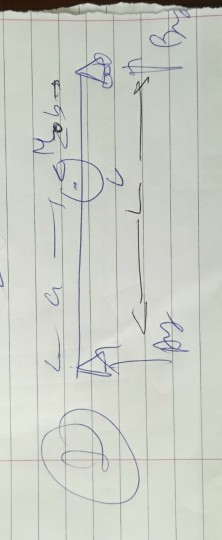
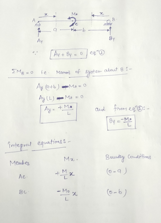
Find the reactions and write the integral with correct boundaries
simply supported beam with applied moment Mo applied
at some distance a
Homework Answers
Add Answer to:
Find the reactions and write the integral with correct
boundaries
simply supported beam with applied moment...
A simply supported beam ABCD is subjected to a force P and a moment Mo as...
 A simply supported beam ABCD is subjected to a force P and a moment Mo as shown in the figure. All the dimensions are given in the figure, and the weight of the beam is neglected. (a) Draw the free body diagram for the beam, showing all the applied forces, moments and reaction forces. (b) Use the equations of equilibrium to find the reaction forces at A and C P-15 kN Mp- 10 kNm 4.5 m 3m
Find the reactions at the supports for a simply supported beam of length 15 m in...
Find the reactions at the supports for a simply supported beam of length 15 m in which the point load of 180 kN is acting at a distance of 5 m, UDL of intensity 130 kN/m acting at a distance of 7 m both from the right end.
Support Reactions for a point – loaded, Simply Supported Beam lab write Objective only
Support Reactions for a point – loaded, Simply Supported Beam lab write Objective only
A simply supported uniform beam (with length L and flexural rigidity El) carries a moment Mo...
 A simply supported uniform beam (with length L and flexural rigidity El) carries a moment Mo (clockwise) at a distance -21B away from the left end (x-0). Calculate the deflection () and slope (dv/de) at 21/3 by using the Rayleigh-Ritz Method. Assume a deflection curve of the form v-asin(rx/L), where a is to be determined
Consider the simply supported beam and loaded as shown in the M figure. Perform the following:...
 Consider the simply supported beam and loaded as shown in the M figure. Perform the following: 1. Determine the support reactions. 2. Plot SFD and BMD 3. if L=9 m, the beam will fail when the maximum shear force is Vmax= 5 kN or the maximum bending moment is Mmax=22 kN.m. Determine the largest couple moment Mo the beam will support.
DEFINE GIVEN: A simply supported beam 150 11/ 200 lb TTTI - - FIND: Support reactions...
 DEFINE GIVEN: A simply supported beam 150 11/ 200 lb TTTI - - FIND: Support reactions N V, M equations at cut between 6 (origin starts at 1) Shes and moment diagrams (abel all changes) Absolute maximum shear and moment values SOLVE -- M-- VERTEX
Consider the simply supported beam shown in the figure below. Let x be the distance measured...
 Consider the simply supported beam shown in the figure below. Let x be the distance measured from left end of the beam. 1. Determine the vertical reactions at A and C 2. Write the equations for shear and moment for the section of the member between B and C. 3. Draw the shear and moment diagrams for the entire beam, specifying values at changes in loading and locations where the shear is 0. 48 KN B kN/m D internal pin...
For the following simply supported beam (loads in (N) and dimension in (mm)), Find: (a) The...
 For the following simply supported beam (loads in (N) and dimension in (mm)), Find: (a) The reactions at the two supports. (6) Draw SFD and BMD (c) Find the location where the maximum bending moment occurs 600 1000 3200 30 60 75 90 120
Consider the simply supported beam shown in the figure below. Let x be the distance measured...
 Consider the simply supported beam shown in the figure below. Let x be the distance measured from left end of the beam. 1. Determine the vertical reactions at A and C 2. Write the equations for shear and moment for the section of the member between B and C. 3. Draw the shear and moment diagrams for the entire beam, specifying values at changes in loading and locations where the shear is 0. 48 KN 8 kN/m UT 24 kN-m...
Determine the slope at A of the simply supported beam. Use Moment-Area method. EI is constant....
 Determine the slope at A of the
simply supported beam. Use Moment-Area method. EI is constant.
Problem 3: Determine the slope at A of the simply supported beam. Use Moment-Area method. El is constant. 2L 3
Determine the slope at A of the
simply supported beam. Use Moment-Area method. EI is constant.
Problem 3: Determine the slope at A of the simply supported beam. Use Moment-Area method. El is constant. 2L 3
 A simply supported beam ABCD is subjected to a force P and a moment Mo as shown in the figure. All the dimensions are given in the figure, and the weight of the beam is neglected. (a) Draw the free body diagram for the beam, showing all the applied forces, moments and reaction forces. (b) Use the equations of equilibrium to find the reaction forces at A and C P-15 kN Mp- 10 kNm 4.5 m 3m
 A simply supported uniform beam (with length L and flexural rigidity El) carries a moment Mo (clockwise) at a distance -21B away from the left end (x-0). Calculate the deflection () and slope (dv/de) at 21/3 by using the Rayleigh-Ritz Method. Assume a deflection curve of the form v-asin(rx/L), where a is to be determined
 Consider the simply supported beam and loaded as shown in the M figure. Perform the following: 1. Determine the support reactions. 2. Plot SFD and BMD 3. if L=9 m, the beam will fail when the maximum shear force is Vmax= 5 kN or the maximum bending moment is Mmax=22 kN.m. Determine the largest couple moment Mo the beam will support.
 DEFINE GIVEN: A simply supported beam 150 11/ 200 lb TTTI - - FIND: Support reactions N V, M equations at cut between 6 (origin starts at 1) Shes and moment diagrams (abel all changes) Absolute maximum shear and moment values SOLVE -- M-- VERTEX
 Consider the simply supported beam shown in the figure below. Let x be the distance measured from left end of the beam. 1. Determine the vertical reactions at A and C 2. Write the equations for shear and moment for the section of the member between B and C. 3. Draw the shear and moment diagrams for the entire beam, specifying values at changes in loading and locations where the shear is 0. 48 KN B kN/m D internal pin...
 For the following simply supported beam (loads in (N) and dimension in (mm)), Find: (a) The reactions at the two supports. (6) Draw SFD and BMD (c) Find the location where the maximum bending moment occurs 600 1000 3200 30 60 75 90 120
 Consider the simply supported beam shown in the figure below. Let x be the distance measured from left end of the beam. 1. Determine the vertical reactions at A and C 2. Write the equations for shear and moment for the section of the member between B and C. 3. Draw the shear and moment diagrams for the entire beam, specifying values at changes in loading and locations where the shear is 0. 48 KN 8 kN/m UT 24 kN-m...
 Determine the slope at A of the
simply supported beam. Use Moment-Area method. EI is constant.
Problem 3: Determine the slope at A of the simply supported beam. Use Moment-Area method. El is constant. 2L 3
Determine the slope at A of the
simply supported beam. Use Moment-Area method. EI is constant.
Problem 3: Determine the slope at A of the simply supported beam. Use Moment-Area method. El is constant. 2L 3
Most questions answered within 3 hours.
-
Where is the error in this code sequence?
String s1 = "Hello";
String s2 = "ello";...
asked 10 months ago -
Financial data for Joel de Paris, Inc., for last year
follow:
Joel de Paris, Inc.
Balance...
asked 10 months ago -
Consider this reaction:
Al2(SO4)3 (aq)+ BaCl3
(aq) Al2Cl6 (aq)- +
3BaSO4(s) . What is the...
asked 10 months ago -
Suppose that Savneet is considering increasing her
recent random sample from 20 car rentals to 40...
asked 10 months ago -
Trucks arrive at an unloading terminal at an average rate of 120
per hour.
Trucks arrive...
asked 10 months ago -
Why are methanol and ethanol completely soluble in water while
octanol is not very little soluble....
asked 10 months ago -
A facilities manager at a university reads in a research report
that the mean amount of...
asked 10 months ago -
When the CuSO4 is rehydrated by adding water to the anhydrous
compound, is this an endothermic...
asked 10 months ago -
A ray of sunlight is passing from diamond into crown glass; the
angle of incidence is...
asked 10 months ago -
A block of mass 0.249 kg is placed on top of a light, vertical
spring of...
asked 10 months ago -
how do the kidneys compensate in the presences of acidosis
a) trigger hyperventilate
b) reserve acid...
asked 10 months ago -
Question 501 pts
The rental rate of capital to the firm increases. Which of the
following...
asked 10 months ago